
 Skip to content
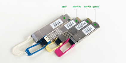
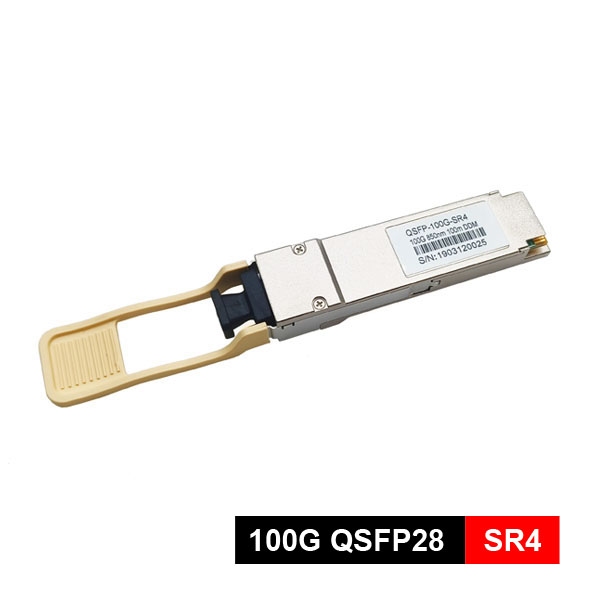
 The 100G QSFP28 module is the core group for upgrading data centers and enterprise networks to 100G. The “28” in QSFP28 refers to each electrical channel supporting a speed of 28Gbps. In practical applications, it uses 4 channels, each carrying 25Gbps of data, totaling 100Gbps. This design allows it to achieve high-density 100G ports on network devices with a compact size.

Yingda can provide QSFP28 form factor pluggable transceiver modules with best QSFP28 price. All products are produced with brand new materials and high-end chips, with 100% pass testing and comprehensive compatibility testing. They are widely compatible with switches and servers from brands such as Mikrotik, Cisco, HPE, Huawei, ZTE, Ruijie, Dell, etc.
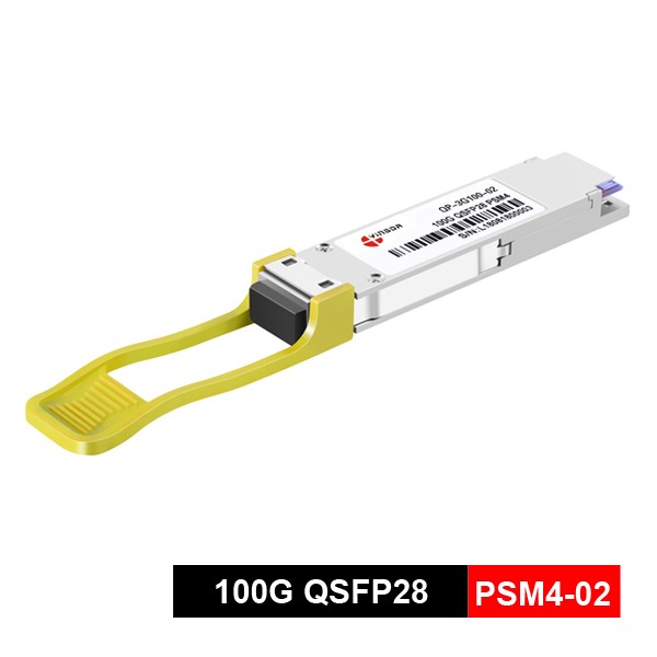
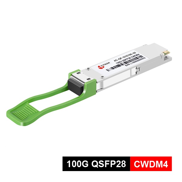
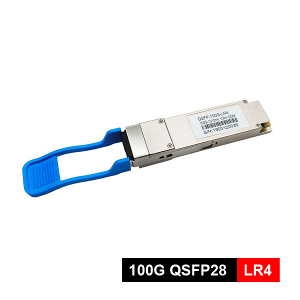
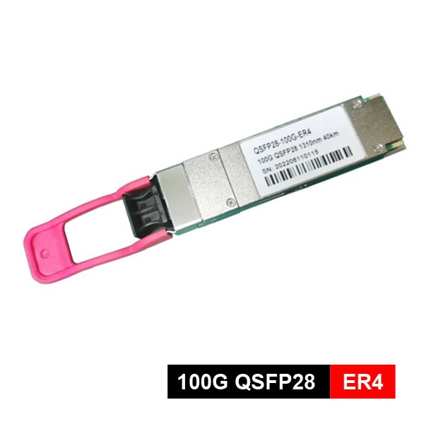

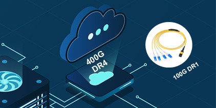
The CAUI-4 is the standard electrical interface for 100G QSFP28 modules, which splits the 100G data stream into four 25G NRZ electrical signal channels. Inside the module, signal processing is performed via a Gearbox (gearbox) or DSP chip. Therefore, the modulation mode includes two options: four 25G NRZ channels and a single 100G PAM4 channel. The industry is also evolving toward more efficient single-channel technologies(single lambda), such as DR1 (500 m) and FR1 (2 km) modules, which utilize a single 100G PAM4 signal. PAM4 further simplifies the design, reduces costs, and enables better upgrades to 400G or higher speeds. Below are some products which use PAM4 modulation that Yingda can supply:
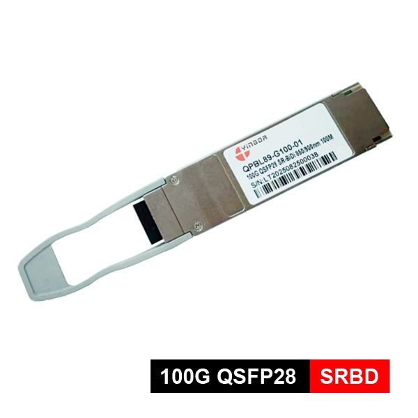
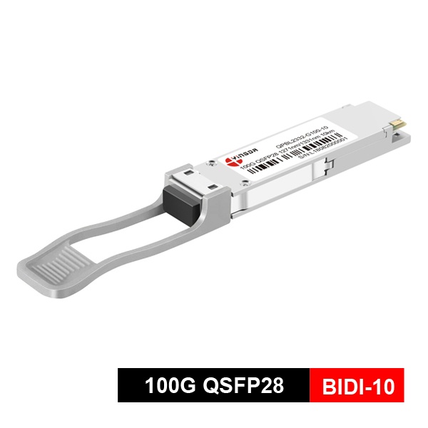
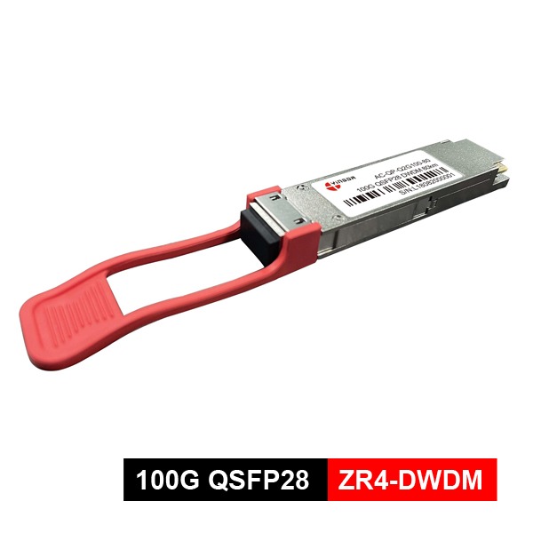
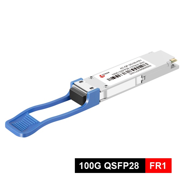
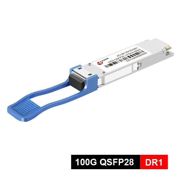
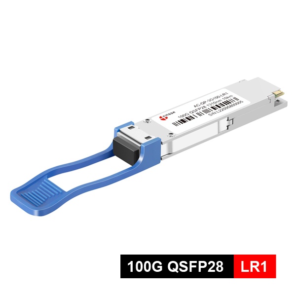
The 100G QSFP28 module family is huge, and there are many different classifications to different distances and scenarios. If classified according to fiber optic interfaces, there are three types: MPO, duplex LC, and simplex LC (BIDI). For the convenience of comparison, Yingda has compiled their core parameters into the following table:
Module Type | Common Standard | Optical Interface | Fiber Type | Maximum Distance | Power Consumption (Approx.) | Typical application |
SR4 | 100GBASE-SR4 | MPO-12 | MMF | 100 m (OM4) | 3.5W | High-speed interconnection between cabinets and servers to switches. |
PSM4 | 100GBASE-PSM4 | MPO-12 | SMF | 500 m | 3.5W | Scenarios requiring single-mode fiber but with distances shorter than 2km. |
PSM4-02 | 100GBASE-PSM4 | MPO-12 | SMF | 2 km | 3.5W | Designed specifically for scenarios that require both breakout (1+4) and cross-building coverage within the campus (up to 2 kilometers) |
PSM4-10 | 100GBASE-PSM4 | MPO-12 | SMF | 10 km | 3.5W | Achieve long-distance 100G to 4x25G breakout |
CWDM4 | 100G CWDM4 MSA | Duplex LC | SMF | 2 km | 3.5 – 4W | Data center interconnect (DCI) fills the gap between SR4 and LR4, offering high cost-effectiveness. |
CWDM4-L | 100G CWDM4 MSA | Duplex LC | SMF | 10 km | 3.5 – 4W | 10 kilometer interconnection across buildings and regions, with standard dual core single-mode fiber resources,. |
LR4 | 100GBASE-LR4 | Duplex LC | SMF | 10 km | 4 – 4.5W | A more cost-effective alternative than LR4. |
ER4 | 100GBASE-ER4 | Duplex LC | SMF | 40 km | 4.5W | Core interconnection of the park, data center to urban nodes |
ZR | Coherent transceiver | Duplex LC | SMF | 80 km | 5.5 – 6W | Operator backbone network, long-distance DCI. |
ZR+ | Coherent transceiver | Duplex LC | SMF | up to 300 km | 5.5 – 6W | The use of coherent technology, tunable in the C-band, is the flagship solution for ultra long distance transmission. |
ZR4 | 100GBASE-ZR4 | Duplex LC | SMF | 80 km | 5 – 6W | The use of coherent technology, tunable in the C-band, is the flagship solution for ultra long distance transmission. |
ZR4+ | 100GBASE-ZR4+ | Duplex LC | SMF | 100 km | 5.5 – 6.5W | Data Center Interconnection (DCI), Metropolitan Area Network, and Telecommunications Backbone Network |
DWDM-80 | 100GBASE-DWDM-ZR4 | Duplex LC | SMF | 80 km | 4.5W – 5.5W | High bandwidth connectivity for Data Center Interconnection;100G Ethernet Metro-Access over DWDM,P to P Access Network |
SRBD | 100GBASE-SR-BD | Duplex LC | MMF | 100 m (OM4) | 4W | Server interconnection or Leaf switch interconnection; Upgrade from 10G/25G/40G to 100G |
BIDI-10 | 100G Lambda MSA 100G-LR | Simplex LC | SMF | 10 km | 3.5 – 4.5W | There is only one backup fiber optic cable in the existing pipeline, but it needs to be expanded to 100G for backbone connections within 10 kilometers across buildings, as well as for connecting distributed units (DU) and core networks. |
BIDI-20 | 100G Lambda MSA 100G-LR | Simplex LC | SMF | 20 km | 4.0 – 4.5W | Suitable for 100G backbone connections and 400G evolution across urban areas and branch offices, or when the leased fiber optic cable has only one core and the transmission distance exceeds the upper limit of a regular 10km module. |
BIDI-40 | 100G Lambda MSA 100G-ER | Simplex LC | SMF | 40 km | 4.5W | Used for direct connection between two data center rooms within 40 kilometers, with 5G backhaul, and when only one single-mode fiber is available and 100G bandwidth is required. |
BIDI-80 | 100G Lambda MSA 100G-ZR | Simplex LC | SMF | 80 km | 6W | Long distance fiber optic leasing and direct connection to urban core network nodes within 80 kilometers. |
FR1 | 100GBASE-FR1 | Simplex LC | SMF | 2 km | 4.5W | Park network interconnection, local data center interconnection, 400G DR4 branch applications, smooth evolution of data centers towards 400G |
DR1 | 100GBASE-DR1 | Simplex LC | SMF | 500 m | 4W | The data center connects Leaf switches and Spine switches internally. |
LR1 | 100GBASE-LR1 | Duplex LC | SMF | 10 km | 4 – 4.5W | 400G to 100G splitter application |
Traditional modules use NRZ (Non Return to Zero) encoding, which is simple and reliable. New modules such as LR1, DR1, and 400G modules often use PAM4 (four level pulse amplitude modulation), which can double the rate with the same number of channels.
In order to save fiber resources, LR4 and ER4 long-distance modules will use WDM technology to multiplex four different wavelength optical signals onto a pair of optical fibers for transmission.
All standard QSFP28 modules support digital diagnostic monitoring (DDM/DOM), which can monitor key parameters such as temperature, voltage, and optical power in real-time, facilitating network management and troubleshooting.
The key to choosing a suitable 100G QSFP28 module is to find the optimal balance between transmission distance, fiber type, equipment compatibility, and budget. YINGDA suggests selecting according to the below steps.
Step 1
This is the most important step. Please accurately measure the fiber link length between two device ports (including the sum of all jumpers and backbone fibers). Different distances correspond to completely different module technologies.
Step 2
Check the fiber optic jumpers and cables you will be using:
Step 3
Step 4
Based on the distance and fiber determined in the previous steps, find the most suitable module type in the table above.
Step 5
Sure, the QSFP28 port is backward compatible with QSFP+(40G) modules and can automatically negotiate to slow down to 40G operation after insertion. But conversely, QSFP+ports do not support inserting QSFP28 modules.
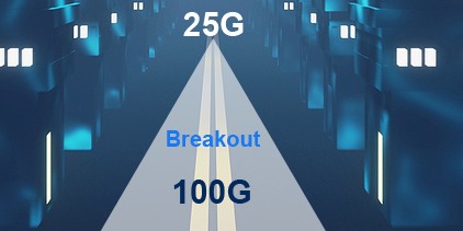
yes, this is called the "splitting" or "Breakout" mode. By using dedicated breakout cables (such as MPO to 4xLC), one 100G port can be connected to four independent 25G ports, making it ideal for connecting high-density servers.
For most optical links, FEC is necessary as it can effectively correct transmission errors and ensure signal quality. But for short distance direct attach cables (DAC), they can be left off.
The main difference lies in the fiber count and usage:
If the existing wiring is MPO interface MMF, choose SR4 directly; If the existing wiring is traditional duplex LC interface MMF, then choose BiDi module, which can upgrade from 10G/40G to 100G without modifying the cable.
It support 30 km transmission. If FEC is enabled, the transmission distance can be further extended to 40 km.
This is usually a false fault. It may be an error in the device reading module register data, or an abnormality in the module's register offset reading function, but the optical transceiver function itself is normal. You can try restarting the port or upgrading the device software. If the problem persists, it is recommended to replace the module for troubleshooting.
Very much needed. Excessive receiving power can burn out the receiver of the 100G optical module. Suitable optical attenuators must be immediately added to the link to reduce the received optical power to within the normal range.
It is likely to be a line sequence (polarity) error. When using MPO to LC breakout cable, it is necessary to ensure that the line sequence is "reversed" (Type B) to ensure that the transmit and receive signals correspond. If multiple jumpers are connected in series, the polarity will "reverse and then reverse" to become straight through, and the connection method needs to be carefully planned.
Very necessary, especially for single-mode optical fibers. The end face of MTP/MPO connectors is very sensitive, and dust or oil stains can directly cause signal loss or an increase in bit error rate. It is recommended to use specialized cleaning tools for regular cleaning.
High productivity efficiency, skilled workers and strict production control ensure timely delivery.
High-precision testing equipment and top industry quality control system ensure high quality standards.
Long-term stable supply chain and cost control that changes in line with market trends ensure the best price
Sorry that there’s no information that interests you. Please fill in the feedback form so that we can improve.