Skip to content
Description
Features of 100gbase fr1
- Compliant with IEEE 802.3bmelectrical specifications (Clause 83E, CAUI-4)
- Supports both FEC and non-FEC modes on the host side
- Supports 100 Gbps data rate
- Up to 2kmreach?over?SMF
- Typical power consumption: 3W
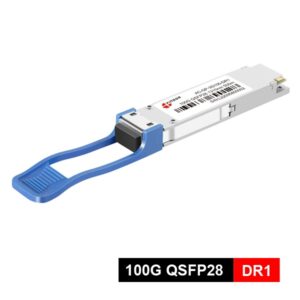
- Hot-pluggable QSFP28 form factor
- Duplex LCconnector
- Operating case temperature range: 0 to 70??C
- RoHS-6 compliant (lead-free)
Standard
- CEI-28G-VSR
- QSFP28 MSA
- SFF-8636
Application
- 100G FR1 is an ideal solution for 100G high-speed channel interconnection between different office buildings and data center buildings within a 500-meter to 2-kilometer area without the need for existing wiring modification;
- For data center interconnection within the same city within a distance of 2 kilometers or less, only 2-core optical fibers are required, which is less costly than LR4 and just the right distance;
- When used in combination with 400G DR4, it connects through MPO-12 to 4LC branch jumper to achieve 1:4 branching, enabling flexible expansion;
- During the upgrade from 100G to 400G, if the distance exceeds 500 meters, FR1 (2km) can be used as a transitional solution without the need for rewiring.
Absolute Maximum Ratings
| Parameter | Symbol | Min | Max | Unit |
| Storage Temperature | – | -40 | 85 | oC |
| 3.3V Power Supply Voltage | – | -0.5 | 3.6 | V |
| Data Input Voltage- Single Ended | – | -0.5 | – | Vcc+0.5 |
| Control Input Voltage | – | -0.5 | 3.6 | V |
| Relative Humidity | – | 5 | 85 | % |
| Rx Optical Damage Threshold / Lane | – | 5 | – | dBm |
Recommended Operating Conditions
| Parameter | Symbol | Min | Typical | Max | Unit |
| Case Operating Temperature | – | 0 | – | 70 | oC |
| Power Supply Voltage | – | 3.135 | 3.3 | 3.465 | V |
| Date Rate per Channel (4*25G NRZ) | – | – | 25.78125 | – | Gbps |
| Date Rate per Channel (2*50G PAM4) | – | – | 53.125 | – | Gbps |
| Bit Error Ratio (BER) with FEC on Bit | – | – | 10-12 | – | – |
| Error Ratio (BER) without FEC | – | – | – | 2.4×10⁻⁴ | – |
| Control Input Voltage High | – | 2 | – | Vcc+0.3 | V |
| Control Input Voltage Low | – | -0.3 | – | 0.8 | V |
| Two Wire Serial (TWS) Interface Clock?Rate | – | – | – | 1 | MHz |
| Differential Data Input / Output Load | – | – | 100 | – | Ohms |
| SM Fiber Length (DR1): | – | 2 | – | 500 | m |
| SM Fiber Length (FR1): | – | 2 | – | 2000 | m |
Optical transmitter Characteristics
| Parameter | Symbol | Min | Typical | Max | Unit | Notes |
| Center Wavelength | ?? | 1304.5 | – | 1317.5 | nm | – |
| Side-Mode Suppression Ratio | SMSR | 30 | – | – | dB | – |
| Average launch power, each lane | LOP | -2.9 | – | 4 | dBm | – |
| Output Optical Modulation Amplitude, per Lane | OMA | -0.8 | – | 4.2 | dBm | – |
| Transmitter and dispersion eye closure (TDECQ), each lane | TDECQ | – | – | 3.4 | dB | – |
| Extinction ratio | ER | 3.5 | – | – | dB | – |
Optical?receiver?Characteristics
| Parameter | Symbol | Min | Typical | Max | Unit | Notes |
| Center Wavelength | ?? | 1304.5 | – | 1317.5 | nm | – |
| Damage Threshold | – | 5.5 | – | – | dBm | – |
| Average receive power | – | -6.4 | – | 4.5 | dBm | – |
| Receive power (OMAouter) | – | – | – | 4.7 | dBm | – |
| Receiver Reflectance | – | – | – | -26 | dB | – |
| Receiver sensitivity (OMAouter) | – | – | – | Equation | dBm | 1 |
| Stressed receiver sensitivity (OMAouter) | – | – | – | -12.5 | dBm | 2 |
| Conditions of stressed receiver | – | – | – | – | – | – |
| sensitivity test: | – | – | – | – | – | – |
| Stressed eye closure for PAM4 (SECQ), lane under test | – | – | 3.4 | – | dB | – |
| OMAouter of each aggressor lane | – | – | – | 3.4 | dBm | – |
Ordering Information
| Part. No | Specifications | ||||||||
| Pack | Rate (Gbps) | Tx (nm) | Po (dBm) | RX | Sen (dBm) | Temp (??) | Reach (KM) | DDM | |
| QSFP28-100G-FR1 | QSFP28 | 100GbE (53.125 GBd) | 1310nm?EML | -2.9~4 | PIN | <-5.3 | 0~70 | 2 | Y |