Parallel Wiring is a cabling solution used in data centers and high-speed networks that employs multi-core optical fibers or multi-channel electrical interfaces to transmit data simultaneously. It contrasts with traditional serial wiring (dual-fiber single-channel) and significantly enhances single-port bandwidth through a “multi-lane parallel” approach.
Serial vs. Parallel: Core Differences
Serial is like a “dual fiber single channel”, while parallel is like an “8-24-lanes multi-fiber highway”.
| Item | Serial wiring | Parallel wiring |
| Transmission method | Serial transmission of a single logical signal | Parallel transmission of multiple logical signals |
| Number of fiber cores per port | 2-core (one transmit, one receive) | 8-24 cores (receive more, transmit more) |
| Interface type | Duplex LC | MPO/MTP (multi-fiber push-onl connector) |
| Channel architecture | 1 Channel | N channel (4/8/12/16) |
| Typical rate | 10G, 25G, 100G (single channel) | 40G, 100G, 200G, 400G, 800G |
| Port density | Lower (larger LC interface) | Extremely high (1U can accommodate 144+cores) |
| Power consumption | Higher (requiring optical module+fiber optic) | Lower (multi-channel shared circuit) |
| Typical Applications | Enterprise Network FTTH, Traditional data center | Ultra large scale data center, AI/HPC cluster |
Why is parallel wiring necessary?
With the arrival of the 400G/800G era, the improvement of single channel speed is facing physical limits (copper wire loss, optoelectronic device bandwidth). Parallel cabling adopts mature 25G/50G VCSEL technology, which achieves bandwidth doubling by increasing the number of channels and reducing the single channel rate requirement. This not only simplifies the design of optical modules, but also avoids serious losses in high-speed signal transmission.
The bandwidth doubling is as follows:
- 400G: 8 × 50G PAM4 or 4 × 100G PAM4;
- 800G: 8 × 100G PAM4 or 16 × 50G PAM4
The core technology of parallel cabling
Parallel cable connector:MTP/MPO
The basis of parallel data cable is MPO/MTP multi-fiber push on connector, which accommodate multi-core optical fibers (4/8/12/16/24 cores) in one interface.
- MTP vs MPO: MTP is an improved version of MPO with better optical performance and mechanical accuracy, and the two are physically compatible.
| Connector type | Fiber count | Typical application | Parallel channels |
| MPO-12 | 12 cores | 40G/100G SR4 | 4Tx 4Rx (8fiber in use, 4 no use) |
| MPO-16 | 16cores | 400G SR8/PSM8 | 8Tx 8Rx (16cores all use) |
| MPO-24 | 24cores | 400G SR8( high density) / 800G | 8Tx 8Rx or 16Tx 16Rx |
There are several MPO/MTP parallel cabling products that Yingda can provide, including:
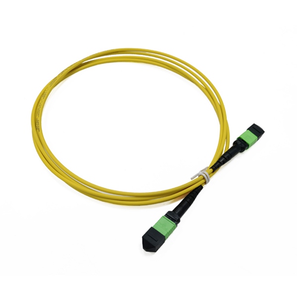
MPO-12/16/24 Trunk cable High density backbone transmission 12-144 cores
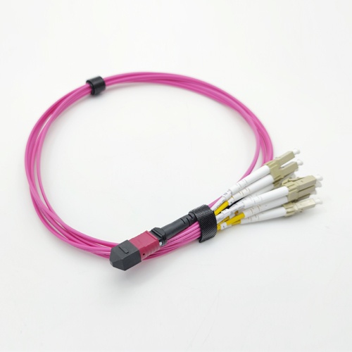
Breakout cable MPO 12 to 4LC, MPO 16 to 8LCPort splitting and flexible scheduling
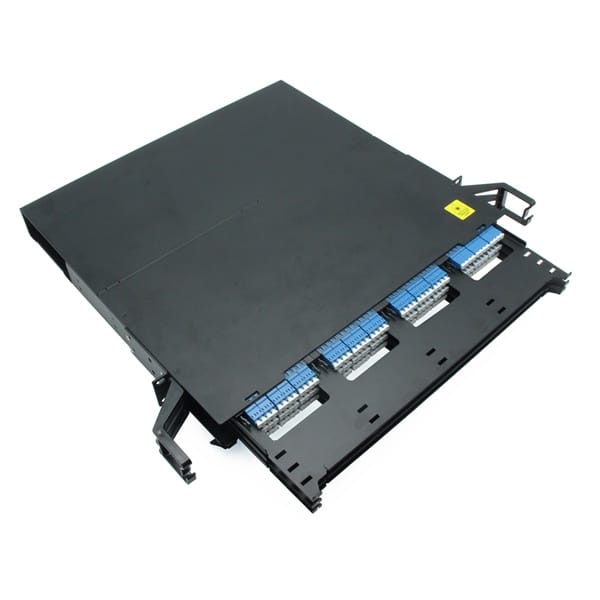
MPO adapter panel1U 4×MPO-24 high density wiring management
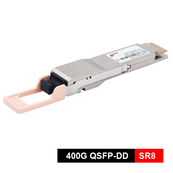
MPO Interface Transceivers400G SR8/DR4/PSM8 photoelectric conversion
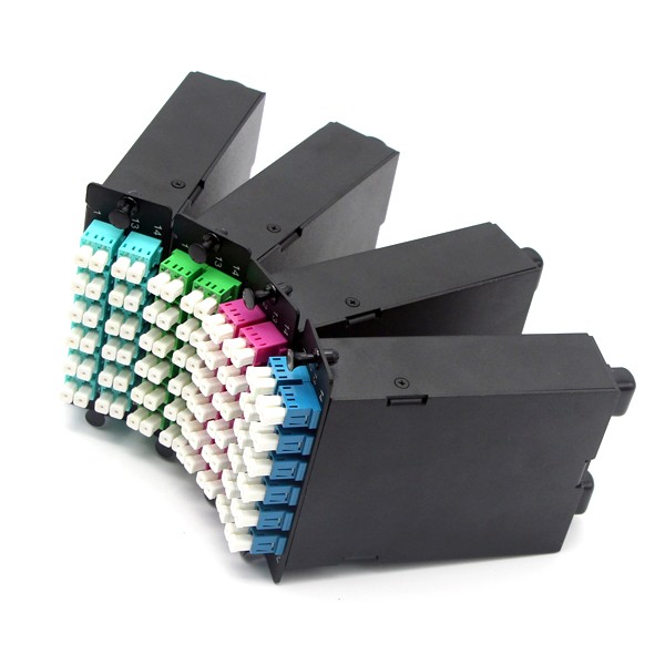
MTP MPO cassette module
12 core/24 core MPO to LC conversion forhigh density wiring
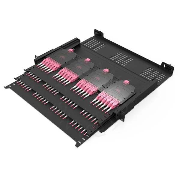
MPO distribution frameHigh density 144 core, 288cores or 576 core, such as 1U, 3U, 4U, etc
Parallel Structure
Parallel cabling relies on multi-channel parallel fiber channel transceivers, and common architectures include:
| Structure | Channel qty | Typical rate | Optical module type | Interface |
| 4×25G NRZ | 4 channel | 100G | QSFP28 SR4 | MPO-12 |
| 4×50G PAM4 | 4 channel | 200G/400G | QSFP56 FR4 / QSFP-DD FR4 | Duplex LC |
| 8×25G NRZ | 8 channel | 200G | QSFP-DD SR8(at the beginning) | MPO-16 |
| 8×50G PAM4 | 8 channel | 400G | QSFP-DD SR8 / PSM8 | MPO-16 |
| 16×50G PAM4 | 16 channel | 800G | QSFP-DD SR16 | MPO-24 |
The core advantage of parallel cabling
- Ultra high bandwidth density: A single MPO-24 interface can carry 800G (16 × 50G), far exceeding LC duplex solutions
- Save cabinet space: 1U space can accommodate 144 cores (6 x MPO-24), with a 300% increase in port density
- Reduce power consumption: Parallel modules share circuits, with power consumption lower than the sum of multiple serial modules
- Simplified deployment: Pre terminated MPO backbone cable, replacing 12 LC LC patch cords with one cable
- Flexible breakout: Supports 1/4 and 1/8 branches to protect investments
- Future oriented: 400G/800G/1.6T are all based on parallel architecture, with smooth evolution
Parallel cabling scheme
1. Classification by transmission medium
| Type | Fiber type | Typical distance | Application scenarios |
| Parallel multi-mode wiring | OM3/OM4 multimode fiber | 70-100 meters | Internal cabinet rooms and TOR Leaf interconnection in data centers |
| Parallel single-mode wiring | OS2 single-mode fiber | 500 meters to 2 kilometers | Park interconnection, DCI short distance |
| Parallel Active Optical Cable (AOC) | Pre terminated multi-core optical cable | 30-100 meters | Short distance, plug and play inside the cabinet |
2. Classified by topological structure
Point to point switch direct connection:
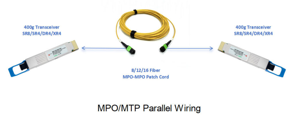
In a 400G data center, parallel cabling is the standard solution for achieving high bandwidth and high-density interconnection, using 8/12/16 MPO/MTP patch cords , without breakout kit, simple and efficient, without branches:
- Spine Leaf interconnection: 400G SR8 + MPO 16 cable parallel wiring, single port bandwidth of 400G, transmission distance of 100 meters.
- TOR to Leaf uplink: 100G SR4 + MTP 12 cable parallel wiring, transmission distance of 100 meters.
- Leaf to Spine interconnection: 400G DR4/FR4 + MPO 12 fiber cable parallel wiring, with a transmission distance of 500 meters.
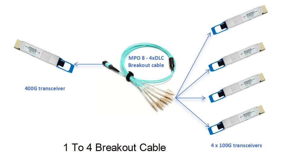
1 to 4 Breakout (most common): 400G → 4 x100G
400G DR4 fiber transceiver → MPO 12 to 4x LC duplex patch cords → 4 x 100G DR1 fiber transceiver
The most common wiring method is to split one 400G port and connect four 100G devices, which not only protects the existing 100G investment but also supports phased network upgrades.
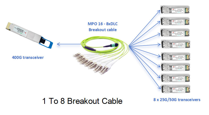
1 to 8 Breakout: 400G → 8 × 25G
400G PSM8 fiber module → MPO 16 to 8 LC fanout cable → 8 × 25G SFP28 fiber module
400G to 8x25G is a commonly used branching scheme in the early days of 400G, with ultra-high density access. One 400G port can be split and connected to eight 25G devices. Note that 400G uses PAM4 modulation, with a single channel 100G rate, while 25G optical modules use NRZ modulation. Therefore, 400G optical modules should remember to use PAM4+NRZ standard chips with Gearbox function.
Challenges and Solutions of Parallel Wiring
| Challenge | Solution |
| Polarity management is complex | Adopting Type B (crossover type) to standardize polarity and simplify inventory |
| High difficulty in cleaning the end face | MPO one click cleaner for 12/16 core end faces |
| Bending radius control | G. 657 anti bending fiber, minimum bending radius 7.5mm |
| Difficulty in troubleshooting | MPO dedicated OTDR, locate specific channels |
| relatively high cost | TCO lower than serial solution during batch deployment, saving wiring time |
Conclusion
Parallel wiring is the cabling standard of the 400G/800G era in data centers – integrating MPO/MTP 8 to 16 fibers into one interface to achieve ultra-high bandwidth of single port 400G / 800G, with a density three times that of traditional LC solutions and an 80% increase in deployment efficiency.
At present, the single channel speed has been continuously upgraded from 25G, 50G, and 100G PAM4. The mainstream parallel solution for 400G uses MPO 24 or MPO 16 cores, while the 800G SR8 is commercially available. The higher density 800G/1.6T will use MPO-32. In the pursuit of lower power consumption, the number of CPOs (co packaged optics) that integrate optical engines with ASICs and eliminate DSP will gradually increase.
FAQ
What are the common wiring solutions for AI training cluster interconnection?
The interconnection of AI training clusters requires high bandwidth and low latency communication between GPUs. Common examples include NVIDIA DGX/H100 clusters with 400G/800G parallel interconnection; InfiniBand NDR: 400G parallel optical module+MPO-16 wiring; NVLink switch: high-density parallel backplane interconnection.
What fibre channel transceivers will be used for 400G parallel cabling?
Commonly used fibre channel transceiver like 400G SR8, SR4, DR4, etc.
Is LC simplex or duplex used for serial wiring?
The serial wiring uses LC duplex connectors. In standard cabling practices for data centers and enterprise networks, data needs to be transmitted (TX) and received (RX) separately through two optical fibers, thus requiring two independent physical channels.