Description
Features of 100G QSFP28 ER4 Lite
- Supports 103.1Gb/s aggregate bit rate
- Digital Diagnostics Monitoring Interface
- Duplex LC optical receptacle
- Up to 30km reach overSMF without FEC on host side
- Up to 40km reach overSMF with FEC on Host side
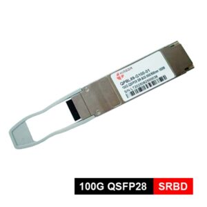
- Hot pluggable QSFP28 MSA form factor
- Receiver: 4x25Gb/s APD ROSA
- Transmitter: cooled 4x25Gb/s LAN WDM DFP/EML TOSA (1295.56, 1300.05, 1304.58, 1309.14nm)
- Compliant with QSFP28 MSA with LC connector
- Commercial operating case temperature range: 0~70℃
- 4x25G electrical interface (OIF CEI-28G-VSR)
- RoHS-6 Compliant
- Power dissipation < 4.0W
Standard
- IEEE 802.3bm
- QSFP28MSA
- SFF-8636
Application
- Metropolitan area network access;
- Data center interconnection (DCI);
- High-performance computing networks;
- Cost-sensitive telecom OTU4 services.
Specification of 100G QSFP28 ER4 Lite
| Absolute Maximum Ratings | ||||
| Parameter | Symbol | Min | Max | Unit |
| Storage Ambient Temperature | TSTG | -40 | 85 | ℃ |
| Operating Humidity | HO | 5 | 95 | % |
| Power Supply Voltage | Vcc | -0.5 | 3.6 | V |
| Damage Threshold, each Lane | THd | -3 | dBm | |
| Recommended Operating Conditions | |||||
| Parameter | Symbol | Min | Typical | Max | Unit |
| Operating Case Temperature | Tc | 0 | 70 | ℃ | |
| Power Supply Voltage | Vcc | 3.135 | 3.3 | 3.465 | V |
| Power Supply Current | ICC | 1360 | mA | ||
| Data Rate,each Lane | 25.78125 | Gbps | |||
| Control Input Voltage High | 2 | Vcc | V | ||
| Control Input Voltage Low | 0 | 0.8 | V | ||
| Data Rate Accuracy | -100 | 100 | ppm | ||
| Link Distance with SMF
(without FEC) |
D1 | – | 30 | km | |
| Link Distance with SMF
(with FEC) |
D2 | 40 | km | ||
| Electrical transmitter Characteristics | |||||||
| Parameter | Symbol | Min | Typical | Max | Unit | Notes | |
| Power Consumption | 4.0 | W | |||||
| Overload Differential Voltage pk-pk | TP1a | 900 | mV | ||||
| Common Mode Voltage (Vcm) | TP1 | -350 | 2850 | mV | |||
| Differential Termination
Resistance Mismatch |
TP1 | 10 | % | ||||
| Differential Return Loss
(SDD11) |
TP1 | See CEI-
28G-VSR Equation 13-19 |
dB | ||||
| Common Mode to Differential
conversion and Differential to Common Mode conversion (SDC11, SCD11) |
TP1 | See CEI-
28G-VSR Equation 13-20 |
dB | ||||
| Stressed Input Test | TP1a | See CEI-
28G-VSR Section 13.3.11.2.1 |
|||||
| Electrical receiver Characteristics | |||||||
| Parameter | Symbol | Min | Typical | Max | Unit | Notes | |
| Differential Voltage, pk-pk | TP4 | 900 | mV | ||||
| Common Mode Voltage (Vcm) | TP4 | -350 | 2850 | mV | |||
| Common Mode Noise, RMS | TP4 | 17.5 | mV | ||||
| Differential Termination
Resistance Mismatch |
TP4 | 10 | % | ||||
| Differential Return Loss
(SDD11) |
TP4 | See CEI-
28G-VSR Equation 13-19 |
dB | ||||
| Common Mode to Differential
conversion and Differential to Common Mode conversion (SDC22, SCD22) |
TP4 | See CEI-
28G-VSR Equation 13-21 |
dB | ||||
| Common Mode Return Loss
(SCC22) |
TP4 | -2 | dB | ||||
| Transition Time, 20 to 80% | TP4 | 9.5 | ps | ||||
| Vertical Eye Closure (VEC) | TP4 | 5.5 | dB | ||||
| Eye Width at 10-15 probability
(EW15) |
tr | 0.57 | UI | ||||
| Eye Height at 10-15 probability
(EH15) |
tf | 228 | mV | ||||
| Optical receiver Characteristics | |||||||
| Parameter | Symbol | Min | Typical | Max | Unit | Notes | |
| Damage Threshold, each Lane | THd | -3 | dBm | ||||
| Average Receive Power, each Lane | -16.9 | -4.9 | dBm | @30km | |||
| Average Receive Power, each Lane | -20.9 | -4.9 | dBm | @40km | |||
| Receive Power (OMA), each Lane | -1.9 | dBm | |||||
| Receiver Sensitivity (OMA), each
Lane |
SEN1 | -13.5 | dBm | For BER
= 1×10-12 |
|||
| Stressed Receiver Sensitivity
(OMA), each Lane |
-12.5 | dBm | For BER
= 1×10-12 |
||||
| Receiver Sensitivity (OMA), each
Lane |
SEN2 | -16.5 | dBm | For BER
= 5×10⁻⁵ |
|||
| Stressed Receiver Sensitivity
(OMA), each Lane |
-14.65 | dBm | For BER
= 5×10⁻⁵ |
||||
| Receiver reflectance | -26 | dB | |||||
| Difference in Receive Power
between any Two Lanes (Average and OMA) |
Ptx,diff | 3.6 | dB | ||||
| LOS Hysteresis | LOSH | 0.5 | dB | ||||
| LOS | Optical De-assert | Pd | -24 | dBm | |||
| Optical Assert | Pa | -26 | |||||
| Receiver Electrical 3 dB upper
Cutoff Frequency, each Lane |
Fc | 31 | GHz | ||||
| Vertical Eye Closure Penalty, each
Lane |
1.5 | dB | |||||
| Stressed Eye J2 Jitter, each Lane | 0.3 | UI | |||||
| Stressed Eye J9 Jitter, each Lane | 0.47 | UI | |||||
Ordering Information
| Part. No | Specifications | ||||||||
| Pack | Rate
(Gbps) |
Tx
(nm) |
Po
(dBm) |
RX | Sen
(dBm) |
Temp
(℃) |
Reach
(KM) |
DDM | |
| QSFP28-100G-ER4 Elite | QSFP28 | 100G | DFP/ EML LWDM | -2.5~4.5 | APD | <-16.5 | 0~70 | 40 | Y |