Skip to content
For many novice buyers or newcomers to the industry, MPO MTP fiber optic cable assemblies can seem quite unfamiliar—and they often lack the knowledge to determine whether the products they have purchased meet quality standards or not. To help you gain a better understanding of MPO MTP Cable, please refer to the article below.
- All you should know about MPO
- How to test the performance of MPO patch cable?
- How to choose good quality MPO MTP patch cable?
- Selection of Common Fiber Optic MPO Cable Sheaths
- Demystifying MPO/MTP Polarity: Type A, Type B, or Type C for 100G/400G Networks?
In addition to above basic knowledge, today we will share with you the industry standards and specifications regarding MPO/MTP Cables.
In modern fiber optic structured cabling systems, the MPO (Multi-fiber Push On) product series—ranging from individual connectors to complex distribution frames—forms a rigorous matrix of standards. Collectively, these standards ensure product mechanical interoperability, optical performance, reliability in extreme environments, and system-level network compatibility.
The following is a list of the core standards applicable to each respective product category:
MPO Connector & Adapter
As the physical cornerstone of the entire system, MPO connectors and adapters are primarily governed by standards regarding mechanical dimensions and end-face optical geometry.
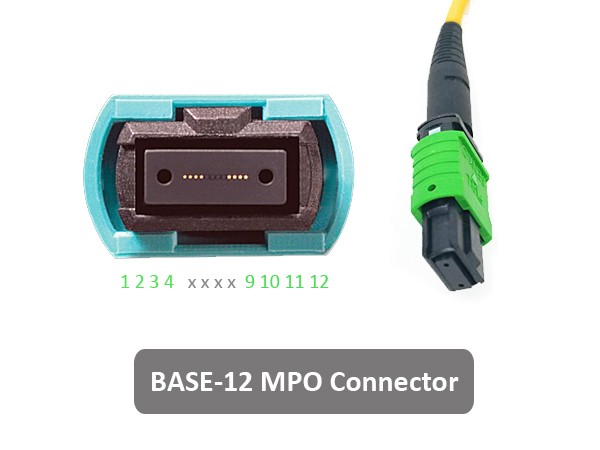

Mechanical Structure and Dimensional Standards:
- IEC 61754-7-1 & 7-2 (International Standards): Specifies the physical dimensions and tolerances for MPO housings, single-row/dual-row MT ferrules, and 0.7mm guide pins, ensuring complete interoperability across different brands.
- JIS C5982 (Japanese Standard): Defines the F13-type multi-fiber connector; its physical dimensions are identical to those specified in the IEC standards.
- TIA-604-5 (FOCIS 5) (North American Standard): Specifies the physical interface requirements for MPO connectors within the North American market.
End-Face Geometry and Optical Standards:
- IEC 61755-3-31: Specifically governs the end-face geometry (curvature, fiber protrusion height, 8° angled polish offset, etc.) of rectangular plastic multi-fiber ferrules used in MPO connectors.
- IEC 61300-3-35: A visual inspection standard for fiber optic end-faces, strictly defining the permissible size of scratches and defects on the polished end-faces of MPO connectors (covering specific zones such as the fiber core [Zone A] and cladding [Zone B]).
Reliability Standards:
- Telcordia GR-1435-CORE: A rigorous “stress-testing” standard for North American telecommunications-grade components, specifying performance requirements regarding aging resistance, salt spray resistance, mold resistance, and operational lifespan within both controlled and uncontrolled environments.
MPO Patch Cords (Patch Cords & Trunk Cables)
MPO patch cords—which comprise the backbone trunk cable and the patch cords at both ends—involve not only the connectors at each termination point but also entail strict requirements regarding fiber-optic physical characteristics, cable flame-retardancy ratings, and fiber polarity.
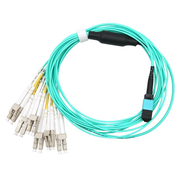

Polarity and Cabling System Standards:
- ANSI/TIA-568.3-D / E (or the older TIA-568-C.3): This serves as the core standard for multi-fiber parallel optics; it strictly defines three polarity wiring methods—Type A (Straight-Through), Type B (Cross-Over), and Type C (Paired Cross-Over)—to ensure the accurate alignment of the optical transmitter (Tx) with the receiver (Rx).
Fiber and Optical Performance Classification:
- IEC 60793-2-10: Specifies the geometric and transmission characteristics of multimode fibers (OM3/OM4/OM5).
- IEC 61755-1: Defines the overall Insertion Loss (IL) and Return Loss (RL) grades for patch cords (e.g., Standard Loss or Low Loss / Elite grades).
Fire Safety and Cable Material Standards:
- UL 1666 / UL 910 (North America): Specifies the flame-retardancy ratings for cable outer jackets, such as OFNR (Riser-rated) or OFNP (Plenum-rated—the highest flame-retardancy rating in North America).
- IEC 60332-1 / 60332-3 (Europe/International): Specifies the flame-retardancy and low-smoke/non-toxic characteristics of Low Smoke Zero Halogen (LSZH) cables.
MPO Cassette Module
A MPO cassette module typically houses a MPO adapter, fan-out patch cords, and standard single-fiber connectors (such as LC or SC) at the front panel. It serves as a transitional component that converts multi-fiber connections into single-fiber connections.

System-Level Application Compatibility Standards:
- IEEE 802.3ba / bm / cd: The internal insertion loss of the cassette module must be strictly controlled to support the network transmission requirements for 40GBASE-SR4, 100GBASE-SR4, or 10G/25G links via fan-out connections.
Structured Cabling Specifications:
- ANSI/TIA-568-C / D / E: Specifies the attenuation limits for connections internal to the module cassette. For instance, the standard defines the maximum allowable total loss for a standard cassette module (which includes a pair of MPO interconnects and front-panel LC interconnects).
Polarity Transition Standards:
- TIA-568.3-D Appendix: Specifies the internal pre-wiring sequence within the module cassette (e.g., Base-8 or Base-12 architecture) to ensure compatibility with the overall system’s polarity design.
Fiber Optic Patch Panel (ODF)
MPO/MTP Patch panels serve as mechanical support and cable management components; their design primarily addresses rack dimensions, installation density, grounding, and labeling management.
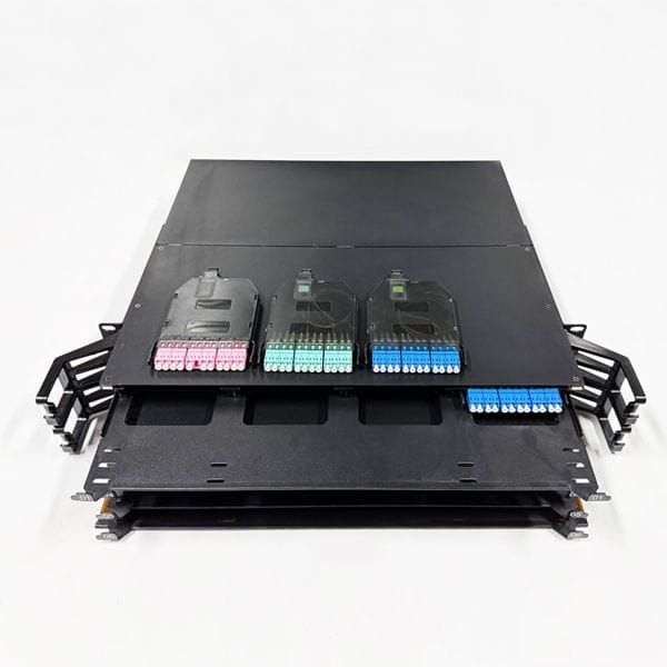
Standards for Data Center and Rack Physical Structures:
- EIA/ECA-310-E (or IEC 60297): Specifies standard 19-inch rack mounting dimensions, unit height (1U/2U/4U), and mounting hole spacing.
Standards for Space and Cable Management:
- ANSI/TIA-569-D: Standards for Telecommunications Pathways and Spaces in Commercial Buildings. This standard mandates requirements for fiber bend radius protection and cable routing tray designs within patch panels to prevent increased signal loss caused by excessive fiber bending.
Standards for Grounding and Labeling Management:
- ANSI/TIA-606-C: Administration Standard for Telecommunications Infrastructure. High-density MPO patch panels must incorporate a standardized labeling and identification system to facilitate subsequent operations, maintenance, and troubleshooting.
- ANSI/TIA-607-C: Grounding and Bonding Requirements for Commercial Buildings. This standard governs the anti-static and grounding designs for high-density metal patch panels.
How to Leverage Standards for Technical Verification?
If you serve as a client-side operations specialist, cabling designer, or product procurement manager, you can align your review of these products with relevant standards by focusing on the following key points:
1. Check Polarity: Verify that both the MPO patch cords and module cassettes consistently claim compliance with TIA-568.3-D (specifically Type A or Type B); mixing incompatible types will result in network connectivity failure.
2. Check Insertion Loss: High-density 100G networks require that both the cassettes and patch cords comply with IEC 61755 Grade B standards or be explicitly designated as “Low Loss.”
3. Check the Data Center Environment: If the application involves an outdoor micro data center, the MPO connectors must be certified under Telcordia GR-1435 (Uncontrolled Environment) standards.