Skip to content
Yes, MTP fanout cables (such as MTP to 4LC or MTP to 8LC) must strictly adhere to the distinction between the three polarity types: A, B, and C.
This is because fiber optic transmission requires a closed-loop configuration to ensure that one end as the transmitter (TX) and the other as the receiver (RX). If the incorrect polarity is selected, the optical signals will become misaligned—for instance, the signal from the transmitting end might be directed toward the receiving device’s transmitting end—consequently preventing the equipment from establishing an optical link or bringing the port online.
Typically, MTP fibre fanout cables feature a multi-fiber MTP connector at one end and a set of single core LC connectors at the other. Due to the “key” design incorporated into the MTP connector, the internal arrangement of its fiber cores is governed by strict industry standards.
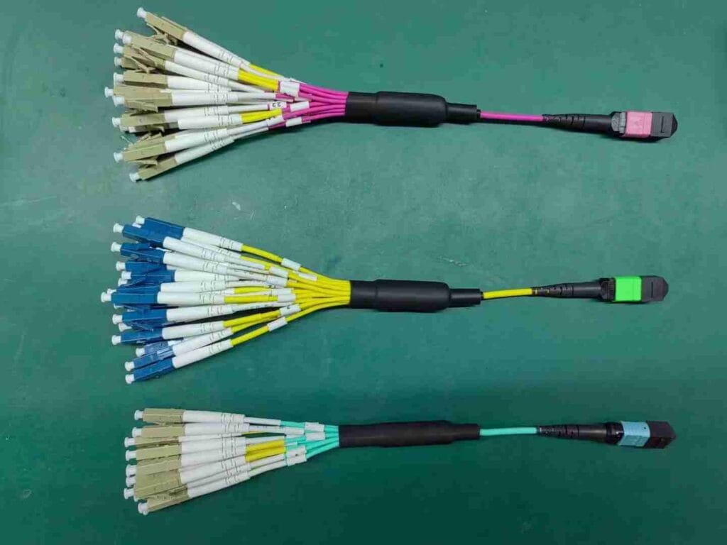
Three Polarity Classifications for MTP Fanout Cables
According to the TIA-568 standard, the polarity of fanout cables is primarily defined by the orientation of the MTP connector’s alignment key and the fiber arrangement at the LC connectors:
Type A (Straight-Through)
- Physical Structure: The MTP end utilizes a “Key-Up / Key-Down” configuration (with the alignment key facing upward at one end and downward at the other).
- Fiber Mapping: The connection from the MTP end to the LC end is completely straight-through. Specifically, the 1st fiber position on the MTP connector connects to the 1st LC connector; the 2nd fiber position connects to the 2nd LC connector; and so on, up to the 12th fiber position connecting to the 12th LC connector.
- Application Scenarios: Commonly used in conjunction with Type A trunk cables and Type B cassettes, or utilized as a foundational connection within certain specific standards.
Type B (Fully Crossed)
- Physical Structure: The MTP connector utilizes a “Key-Up / Key-Up” configuration (with the key on both ends facing upward).
- Fiber Mapping: The fiber sequence is completely reversed. Specifically, the 1st fiber strand of the MTP connector connects to the last pair of LC connectors (e.g., the 12th LC), while the 12th strand connects to the 1st LC.
- Application Scenarios: This is the most commonly used polarity for fanout patch cables! This is because the vast majority of scenarios involving direct 40G/100G connections—or extensions via a Type B trunk network—require a TX/RX signal crossover at the breakout end, which is achieved through the Type B configuration.
Type C (Pair Flipping)
- Physical Structure: The MTP connector side also utilizes the “Key-Up / Key-Down” configuration.
- Fiber Mapping: The internal fiber cores are cross-connected in pairs. Specifically, Fiber 1 and Fiber 2 are swapped at the LC connector end (1-2, 2-1); Fiber 3 and Fiber 4 are swapped; and so on.
- Application Scenarios: This type is now rarely encountered in current mainstream 40G/100G/400G parallel fiber cabling systems. It is primarily used in traditional dual-fiber (10G) backbone systems, where the “pair flipping” mechanism naturally fulfills the transmit/receive requirements of traditional single-mode and multi-mode dual-fiber links.
| Polarity Type | Mapping Logic (MTP End-to-End) | Fiber Transmission Path (Tx/Rx) | Primary Application Scenarios | Common LC Patch Cord Configurations |
| Type A (Straight-through) | P1→P1, P2→P2 … | Requires additional crossover patch cords to complete Tx/Rx pairing | Traditional structured cabling, where signal crossover is achieved via patch panels. | Use an A-B (crossover) patch cord at one end. |
| Type B (Cross-over) | P1→P12, P2→P11… | Tx/Rx pairing is automatically completed within the MTP cable | Parallel optical modules (e.g., QSFP+ SR4)—the most common type found in modern data centers. | No special handling required; standard A-B patch cords can be used at both ends. |
| Type C (Paired Cross-over) | Adjacent Fiber Core Position Crossover (P1 ↔P2) | The cable performs the flip for each duplex link pair | Limited applicability; primarily used in traditional duplex applications, such as early Gigabit Ethernet. | Standard A-B patch cords can be used at both ends. |
Common MTP to LC Fiber Cable Configurations and Polarity Selection
In practical cabling scenarios, MTP to LC fiber cable connections are primarily established using either “harness/fanout cables” or “ cassette modules”. When selecting the appropriate polarity, the following common scenarios serve as useful references:
Direct Connection (Harness/Fanout Cable)
- Scenario: A QSFP+ 40G optical transceiver is directly connected to four SFP+ 10G devices.
- Polarity Selection: Type B. This configuration utilizes a male-to-female mating scheme; the MTP connector end is typically male (featuring guide pins) and connects to the QSFP+ optical transceiver.

Connection via FHD Patch Panels (MTP Cassettes)
- Scenario: Utilizing MTP trunk cables, the connection is converted to LC interfaces at both ends via MTP cassettes to connect to standard network switches and similar devices.
- Polarity Selection:
- Type A Cabling Method: Use a Type A trunk cable + Type A cassettes at both ends.
- Type B Cabling Method: Use a Type B trunk cable + Type A cassettes at both ends.

Complex High-Speed Applications (e.g., 400G SR4.2)
- Scenario:Implementing 400G transmission over an 8-fiber MTP connector requires distinguishing between two distinct wavelengths: 850 nm and 900 nm.
- Polarity Selection: It is essential to carefully consult the equipment manual; in this scenario, the situation is more complex, as—in addition to physical polarity—the pairing of wavelength channels must also be taken into account.
Polarity Specifics of 8 Fiber MTP Fanout Cables
MTP-4LC duplex fanout cables are commonly utilized in 40G (QSFP+) or 100G (QSFP28) networks. Although they are designated as BASE-8 connectors, they actually employ standard MTP 12 fiber connectors. When using these cables, please observe the following points:
① The optical transceiver modules utilize only fibers 1–4 (for transmission) and fibers 9–12 (for reception) of the MTP connector; fibers 5–8 in the middle remain unused.
② To ensure that fibers 1–4 (TX) from Switch A align precisely with fibers 9–12 (RX) on Switch B, the entire link path must incorporate a “flip” at one—and only one—specific point.
③ If your backbone cabling consists entirely of straight-through (Type A) cables, you must select a Type B breakout cable; otherwise, the optical link will fail to establish a connection.
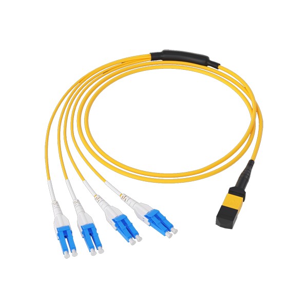
Key Usage Guidelines
To ensure the stable operation of the system, please pay close attention to the following points:
- Clarify Link CoMTPsition: Accurately identifying whether the network link consists of direct-connect breakout cables or a combination of trunk cables and module cassettes is the fundamental basis for selecting the correct polarity method.
- Observe Male/Female Matching (Pin/No-Pin): Mismatched connectors are a common cause of link failure. The basic principle is as follows: Active devices (such as optical transceivers) typically feature built-in male connectors (with pins) for alignment; therefore, the connecting cables should utilize female connectors (without pins).
- Verify Polarity Markings: In addition to standard polarity conventions, some module cassettes or cables offer more flexible polarity configurations—such as options labeled A/AF, B/B1/B2, U (Universal Polarity), etc. It is recommended to verify these configurations by consulting the specific product documentation.
Conclusion
1. The core polarity of MTP to LC fanout cables is defined by the TIA-568 standard, and divided into three types: Type A (Straight-Through), Type B (Cross-Over), and Type C (Pair-Flipped). This standard must be consistently adhered to across the entire link—including patch cords, distribution panels, and active equipment—to ensure proper signal transmission and prevent “light-on-but-no-link” failures.
2. Type B has emerged as the mainstream choice in MTP to LC cabling deployments due to its simplicity when paired with parallel optical transceivers (as it requires no specialized patch cords). However, when making a final selection, it is imperative to prioritize the specific design requirements of the network equipment and cabling scheme to ensure that the polarity, connector gender (male/female), and fiber type are perfectly matched across the entire link (including trunk cables, module cassettes, and breakout patch cords).