What is OPGW Cable & Its Key Features?
Optical Ground Wire, commonly known as OPGW cable, is a dual-functioning cable used in modern power grid construction. It serves as a conventional overhead ground wire while providing a fiber optic communication pathway. Understanding the meaning of OPGW fiber systems involves recognizing their unique ability to blend power grid protection with high-speed data transmission.
Key features of high-quality OPGW cable include:
- Superior Mechanical Strength: The armored layer provides excellent tensile strength, mitigating wear, tensile stress, and lateral pressure to shield inner optical fibers from external forces.
- Excellent Electrical Performance: It features remarkable lightning discharge resistance and short-circuit current overload capacity, ensuring stable operation during grid faults.
- Direct Replacement Capability: It can directly replace traditional overhead ground wires on existing high-voltage lines without modifying the original tower structures.
- Cost Efficiency: Combining communication infrastructure with power lines significantly reduces transmission network construction and engineering costs.
- Lightweight Design: Optimized cable diameters and light unit weight avoid placing heavy external loads on power towers.
- Wide Operating Temperature: Designed to operate reliably under extreme weather conditions ranging from -40°C to +70°C.
Key Engineering Considerations for OPGW Selection
Selection of Fiber Optic Outer Sheath Materials
Choosing the appropriate outer sheath is critical for environmental resistance and thermal stability. The table below outlines the trade-offs between the three primary options:
| Material | Cost | Requirements | Short-Term Temp Rise Ability (Short-Circuit) |
|---|---|---|---|
| Plastic tube (organic synthetic) | Low | Requires at least two layers of armor to meet UV protection demands. | \(<180^{\circ }\text{C}\) |
| Aluminum tube | Lower | Low impedance; increases armor layer capacity to handle short-circuit currents. | \(<300^{\circ }\text{C}\) |
| Stainless Steel tube | High | Thin walls allow more fiber cores to be packed inside safely, reducing unit core costs for high-density setups. | \(450^{\circ }\text{C}\) |
Mechanical & Electrical Equivalence in Line Retrofitting
When replacing an old line ground wire with OPGW cable, engineers must adhere to the principle of electrical and mechanical equivalence. The new cable’s parameters—including outer diameter, unit weight, ultimate tensile strength (RTS), elastic modulus, coefficient of linear expansion, and short-circuit current rating—must align closely with the original overhead line. This ensures a safe clear distance between the OPGW and phase conductors, minimizing retrofitting work on existing tower heads.
Core OPGW Cable Specifications & Loose Tube Structures
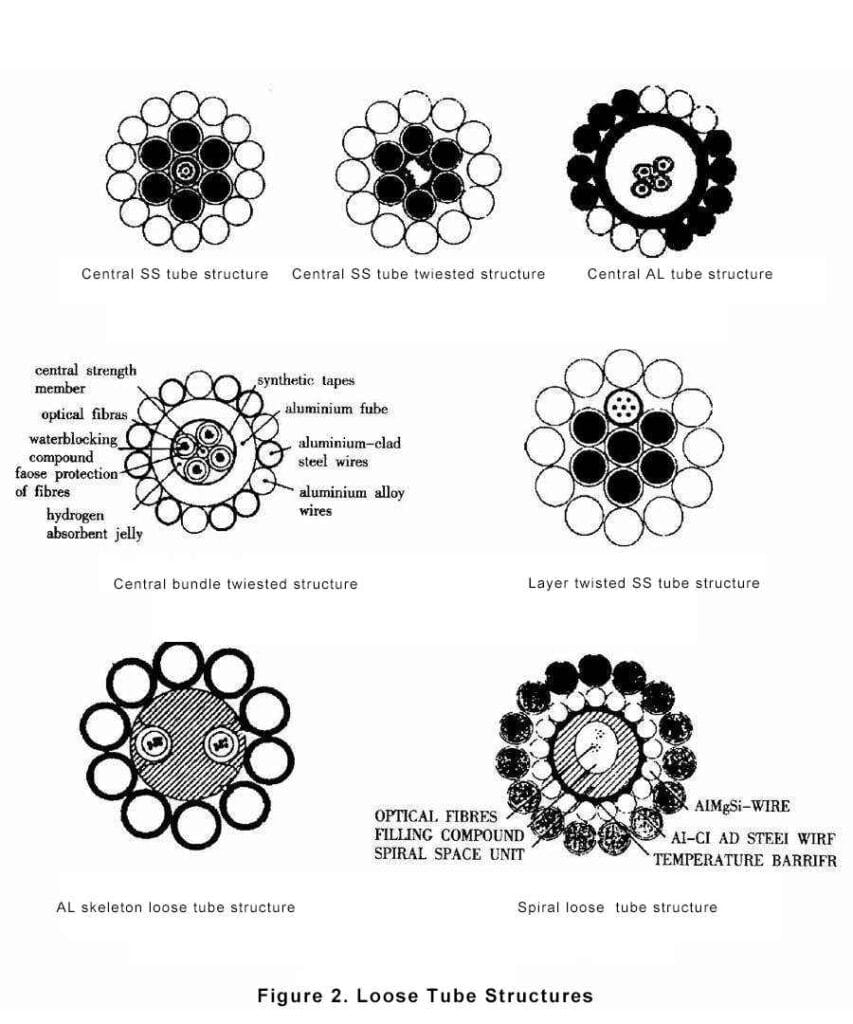
When reviewing an opgw cable specification sheet, the core internal geometry is just as important as the external armor. Engineers must specify loose tube structures rather than tight-buffered options.
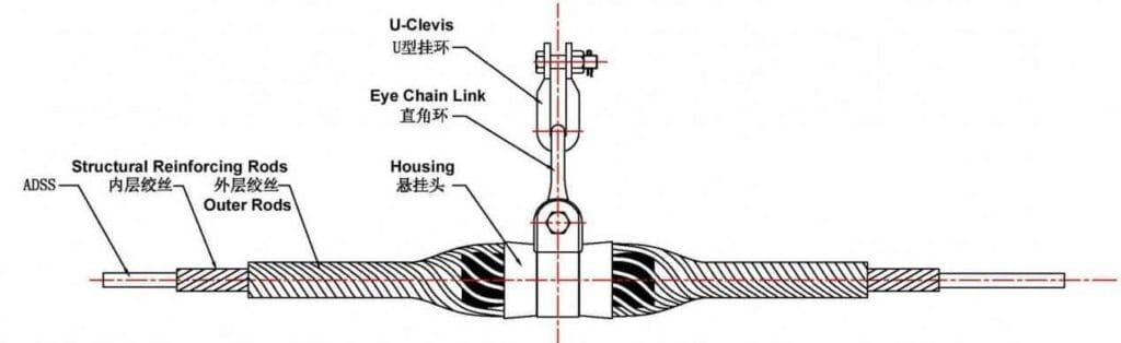
The installation and construction of OPGW optical cable is similar to the installation of ADSS optical cable, and the use of fittings is almost the same, except for the different hanging points. OPGW optical cable should be installed at the position of overhead ground wire. The intermediate joint position of the optical cable line must be placed on the tension tower through a distribution plate.
In the above multiple fiber optic cable selection applications, it is also important to pay attention to one thing in common: choose loose sleeve structure fiber optic cables instead of tight sleeve structure fiber optic cables. Because optical fibers can have a certain amount of excess length inside the loose tube, the control range is between 0.0% and 1.0%, and the classical value is 0.5% to 0.7%. When the optical cable is stretched during construction or under the action of gravity and wind, as long as the stretching length of the optical cable is within the remaining length range, the optical fiber has strain capacity and does not bear tension, thereby ensuring that the transmission quality of the optical fiber is not affected by external forces.
OPGW Construction Method
Even though there is no significant difference in construction methods and requirements between OPGW and ground wire, OPGW also carries the entire length of optical fiber, so there are special requirements for folding, bending, and installation. The most commonly used construction method outside of China now is the tension pay off method.
New Line: Prepare devices such as tension traction equipment, crossing frames, traction ropes, guide pulleys, etc. during the installation of wires and ground wires to achieve maximum resource utilization efficiency. The traditional installation method involves the use of tension machines and traction machines to apply main and auxiliary traction forces. Under the monitoring and guidance of the control system, the OPGW is smoothly laid out and installed on each tower at a relatively stable speed of 10-20 m/s. Installation technicians perform excellent tension section tensioning and observe the scale in the observation gear. After verifying the sag tension gauge data, proceed with installing the tension clamp and then install the suspension clamp. After the continuity test, the installation work of OPGW has come to an end. It is worth noting that when tightening the cable, especially in cases with large height differences, in order to protect the cable from collision with the pulley when it is lifted, it is necessary to tighten it with a cable.
OPGW Cable Splicing
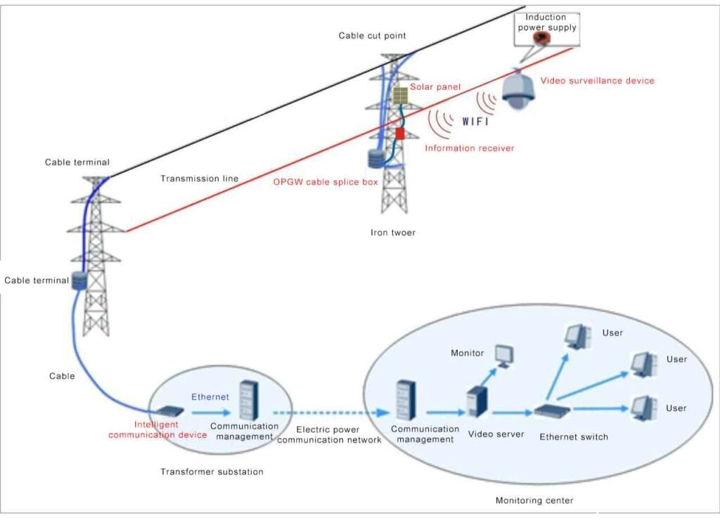
Fiber optic cable splicing is a key process in OPGW fiber optic cable construction, and its quality will directly affect the transmission quality of the line. In OPGW failures that have occurred, the occurrence rate of joint failures is very high. The occurrence of faults not only depends on the method and quality of the fiber optic cable connection sheath, but also includes the internal fiber optic joint reinforcement protection method and material quality, as well as the fiber optic cable splicing process and the sense of responsibility of the splicer. The basic method of OPGW optical cable splicing is the same as that of general optical cable splicing, but there are also differences, and the requirements are increasingly strict. Quality requirements for splicing materials: OPGW optical cables are installed on the same pole as high-voltage lines, and the cables themselves are made of corrosion-resistant materials. Therefore, their splicing sheaths must also be judged products, which should not only have good waterproof and moisture-proof properties and certain mechanical properties, but also have certain resistance to electrical corrosion. The lifespan of the junction box should be greater than the service life of the OPGW.
Installation requirements: In order to prevent human damage, the fiber optic cable splice box must be installed at a height of at least 6 meters above the ground. At the same time, due to the special nature of OPGW fiber optic cables, more surplus cables need to be reserved, and surplus cables and splice boxes should be selected in places that are easy to lay, such as the horizontal grid of the iron tower. The joint box should have the function of non drilling installation and fastening on the tower, and the fixing must be beautiful and reliable.
Connection loss requirement: The connection loss of fiber optic connectors should be lower than the internal control index, and testing should be carried out as much as possible while connecting to ensure that the connection loss of each fiber optic channel meets the design requirements. To effectively control the quality of fiber optic cable joint splicing, the fusion splicer reminds that splicing attenuation can only be used as a reference value. Optical time domain reflectometry (OTDR) should be used to monitor from two directions, and the joint attenuation should be taken as the average value.
OPGW Cable Selection Criteria
- It is necessary to meet the requirements of meteorological conditions, its own tensile strength requirements, and the allowable design load requirements of the iron tower.
- Key technical data to be considered in OPGW design include fiber type, number of fiber cores, cable diameter, cable cross-sectional area, cable unit mass, ultimate tensile strength, short-circuit current, DC resistance, elastic modulus, thermal expansion coefficient, annual average operating stress, minimum bending diameter, maximum reel length, etc.
- Under the conditions of an ambient temperature of+15 ℃, no ice, no wind, and consistent sag with another ground wire, OPGW optical cable can be selected.
- OPGW allows for the determination of short-circuit current. First, determine the equivalent time of the short-circuit current. Typically, for a 220kV line with a high short-circuit current, the equivalent time of the fault current can be considered as 0.3 seconds. Based on the short-circuit current provided by the system, calculate the total short-circuit current of the line entering the ground, distribute the short-circuit current between OPGW and another ground wire, and verify the thermal stability value of OPGW and another ground wire short-circuit at the outlet of the substation. When a single short circuit occurs on the line, a brief high current appears on the overhead ground wire, which generates heat and raises the temperature of the optical cable and shunt line. Due to the short duration of the current, heat will not dissipate into the surrounding environment, resulting in an increase in wire temperature. When the temperature of the wire exceeds its allowable temperature, it will seriously affect safe operation. So meeting the thermal stability requirements is a key condition for determining OPGW and splitter lines.
For OPGW, the manufacturer usually provides the permitted short-circuit current and temperature, and we only verify them. OPGW can select the appropriate section based on the short-circuit current situation at each point of the line.
- OPGW should have a good level of lightning resistance. When lightning strikes OPGW, communication quality should not be affected, and metal parts should not be broken.
OPGW Cable Related Key Issues
Partition and reserved length
Because fiber optic signals experience certain attenuation after passing through each joint, in practical engineering design, OPGW is usually produced with a fixed length and cannot be spliced in the middle. The joint must use a specialized splice box. Therefore, the segmentation of OPGW should be comprehensively considered based on factors such as the route conditions of the main line, construction site, tower type, and manufacturing and transportation conditions.
When designing, the number, model, and length of fiber optic cable reels should be indicated in the OPGW construction schedule. The length of each fiber optic cable needs to consider the impact of cable sag, as well as the reserved length for splice boxes and entry points. Usually, when there is a splice box pole position, an additional 60m is considered, while when entering the substation, a reserved length of 150m is considered.
During the maintenance process of OPGW, it is necessary to extend the optical cable when reconnecting and moving locally. Therefore, appropriate reserved lengths should be made in the OPGW design length at the joint, complex sections, and critical crossings.
Mechanical Calculation
According to the actual engineering meteorological conditions, OPGW optical cables must meet the electrical and mechanical usage requirements: ① OPGW design safety factor is greater than the conductor safety factor; ② The distance between the central conductor and OPGW in the span meets the requirement of S ≥ 0.012L+1 in the regulations under 15 ℃ temperature and windless conditions; ③ It is appropriate to consider maintaining the same level of sag as possible with another ground wire under the above conditions. Based on the above requirements, calculate the characteristic curve and installation curve of OPGW optical cable [2,3].
Initial Advantages and Reasons
After the OPGW optical cable is subjected to tension, it will undergo plastic elongation, which will cause an increase in sag within the cable and reduce the safe distance between the OPGW optical cable and the conductor. Therefore, compensation must be considered during the construction process.
The effect of plastic elongation of OPGW optical cable on sag can be referred to in Article 7.0.6 of the Technical Code for Design of 110-500kV Overhead Transmission Lines, and cooling compensation treatment can be carried out according to the manufacturer’s requirements.
Anti vibration
Breeze vibration is a common occurrence of eddy current backflow in overhead conductors, ground wires, and overhead optical cables. The mechanical principle of gentle wind vibration is that stable stratified wind occurs when passing through cylindrical objects (such as optical cables). When the wind blows on a cylindrical object, layered and staggered vortices behind it create a certain pressure difference, which causes the cylindrical object to move in a direction perpendicular to the direction of the wind. If the eddy current frequency is consistent with the natural frequency of the optical cable, the wire will experience slight wind vibration. This kind of gentle wind vibration poses a fatigue hazard to optical cables.
Common OPGW isolators include anti vibration hammers, anti vibration whips, damping line anti vibration balls, and anti vibration rings. Based on existing data, the key components used for fiber optic cable vibration isolators outside of China are vibration dampers and vibration whips. The anti vibration hammer is a frequency adjustable shock absorber that has a very effective anti vibration effect on large-diameter cables. Its principle is to dynamically absorb energy. Anti vibration whip is a common shock absorber nowadays, which is very effective in reducing high-frequency vibration of small diameter cable lines. The anti vibration whip dissipates the vibration energy by colliding with the cable, thereby achieving the effect of reducing the wind induced vibration of the transmission line. Now on OPGW fiber optic cables, both anti vibration hammers and anti vibration whips are used.
Hardware and Accessories
The key supporting hardware for OPGW includes suspension clamps, tension clamps, dedicated grounding wires, anti vibration hammers, down conductor clamps, clamps, splice boxes, thermoplastic sleeves, etc., which are usually provided by fiber optic cable manufacturers or suppliers. In order to ensure the reliable hanging of OPGW optical cables on the tower, it is usually designed and assembled with corresponding fittings according to the actual situation of the tower hanging holes.
Grounding
OPGW grounding is a small but crucial part, and many designers often easily overlook this issue. OPGW is reliably grounded on each tower through a dedicated grounding wire. The hardware string is connected to a dedicated grounding wire through a parallel groove clamp, and the other end of the grounding wire is fixed to the reserved hole of the tower grounding frame with bolts. Usually, one grounding wire is configured for hanging metal fittings, and two grounding wires are configured for tension resistant straight through and disconnected connections.
FAQ
How to choose another ground wire to match with OPGW Cable?
Simply increasing the OPGW cross-section to meet the short-circuit current requirements is not only uneconomical, but also highly incompatible and mismatched with another ground wire. The solution is to use another ground wire with good conductivity and good conductor, because its resistance and self impedance are low, allowing more current to be distributed to this ground wire, reducing the current passing through the OPGW and playing a good role in diversion. Even if the resistance of the shunt line can be reduced very low, its inductance decreases slowly, so the effect of the shunt line is somewhat limited. Like OPGW, shunt lines can be selected in sections based on the short-circuit current situation at each point of the line. It should be noted that when changing the model of the shunt line, more current is allocated to the OPGW due to the thinning of the shunt line, resulting in a sudden increase in OPGW current. Therefore, the selection of shunt lines needs to be repeatedly calculated.