Skip to content
From the “Method B of the TIA-568 standards (Structured Cabling System)”, we have gained a deeper understanding that in the TIA-568 standard, among three main fiber polarity methods for MPO/MTP backbone cables: TYPE A, TYPE B, and TYPE C, Method B is the most commonly used cabling scheme in data centers.
While in practical network engineering, if a “MPO 12 to 4xLC duplex breakout cable“ is directly used to interconnect the A-end switch (40G QSFP+) with the B-end server/switch (4 x 10G SFP+) without using MPO patch panels and MPO trunk cables, the cabling scheme will become very direct.

At this point, without the “back and forth flipping” of the intermediate multi-level backbone, the polarity crossing must be completed in one go within this breakout cable.
The following is the complete wiring and procurement white paper for implementing this scenario:
Core Conclusion: It is necessary to purchase “QSFP+ dedicated transceiver crossover cable”
In this direct connection scenario, you ABSOLUTELY CAN NOT buy Type A or Type C breakout cables defined by the standard multi-mode backbone standard, nor can you blindly tell the manufacturer that you want the standard “Type B”.
You must customize or purchase “QSFP+ to 4 x SFP+ dedicated polarity breakout cable” (commonly known as QSFP+ 40Gb Breakout Cable Type B in the industry) from the manufacturer.
Why?
Because the physical definition of a 40G QSFP+ optical module is: full emission (Tx) from holes 1-4 and full reception (Rx) from holes 9-12. When this dedicated breakout cable is shipped, the internal wiring harness cable has already been crossed: pairing the Tx on the left and Rx on the right, and forcibly aggregating them into each dual LC connectors.
Dedicated 40Gb Breakout Cables Internal Line Sequence Mapping
When the positioning key of the MPO end is facing upwards (connected to a 40G QSFP+ module), the strict correspondence between its 8 fiber cores leading out to 4 LC duplex connectors (DLC 1~DLC 4 connected to 4 x 10G SFP+ modules) is as following:
| 4 x Dual LC connector | LC connector A/B ends (10G) | Corresponding MPO physical hole(40G) | Final link status |
| DLC 1 (Route 1) | Channel A | P1 -Tx | Integrated receiver and transmitter(Insert into 1st SFP+ module) |
| Channel B | P12-Rx | ||
| DLC 2 (Route 2) | Channel A | P2-Tx | Integrated receiver and transmitter(Insert into 2nd SFP+module) |
| Channel B | P11-Rx | ||
| DLC 3 (Route 3) | Channel A | P3-Tx | Integrated receiver and transmitter(Insert into 3rd SFP+module) |
| Channel B | P10-Rx | ||
| DLC 4 (Route 4) | Channel A | P4-Tx | Integrated receiver and transmitter(Insert into 4th SFP+ module) |
| Channel B | P9-Rx |
✅ Note: The holes 5, 6, 7, and 8 in the middle of the MPO ferrule are empty and not equipped with optical fibers.
Below, we will list two solutions based on the different locations of the four 10G SFP+terminals, and see which products will be used in each solution, as well as their respective precautions. We hope this will be helpful for your future engineering design:
Solution 1: Four 10G SFP+ terminals located adjacent to each other in the same cabinet
Four 10G SFP+terminals located adjacent to each other in the same cabinet is the most ideal scenario for local centralized cabling, which can greatly simplify the specifications of cable enclosures.
1. Physical structure: Recommend “Mini Cable Breakout ”
- Specification Recommendations: For the main MPO cable, recommend a 3.0mm round outer jacket mini cable with 12 bare fibers inside and breakout 4pcs 2.0mm or 0.9mm pigtails (2.0mm is recommended for better mechanical strength and resistance to breakage).
- No Armoring Required: Since the cables are routed entirely within a single cabinet and do not cross the server room bridge, there is absolutely no need to purchase expensive, rigid armored cables with rodent-resistant sheathing. Standard PVC (OFNR) or Low Smoke Zero Halogen (LSZH) materials are sufficient. Learn more
2. Fan out Length: Recommended to be 0.5 meters
- Spacing Calculation: Within a single cabinet, the vertical physical distance between devices located in adjacent positions (such as servers or switches deployed in 1U to 4U increments) is extremely short.
- Length Selection: When placing a custom order with the manufacturer, specify a “fan-out length” of 0.5m for the LC-connector end.
- Why This Matters (Avoiding Pitfalls): Under no circumstances should you order a fan-out length of 1m or longer. If the fan-out section is excessively long, routing cables between adjacent devices will result in a massive accumulation of loose, thin LC fibers along the sides or rear of the cabinet. This not only obstructs airflow and hinders heat dissipation but also creates a high risk of accidental damage—specifically, the fibers being snagged and severed during future maintenance tasks (such as inserting or removing adjacent modules).
3. Labeling and Error-Proofing Management (Crucial)
Since all four LC duplex connectors are plugged into adjacent ports, if the labels were to detach, troubleshooting network faults later on would become a disaster.
- Procurement Requirement: Request the manufacturer to affix clear heat shrinkable numerical markings (typically labeled 1, 2, 3, 4 or P1, P2, P3, P4)—to all four LC duplex connectors prior to shipment.
- Physical Error-Proofing: If possible, request that the manufacturer provide color-coded LC pigtails or color-coded bend-relief boots (e.g., blue for Channel 1, orange for Channel 2, green for Channel 3, and brown for Channel 4—corresponding precisely to the first four colors of the standard color spectrum). This allows for immediate visual identification of which channel corresponds to which terminal device.

4. Minimalist Alternative Solution: AOC (Active Optical Cable)
In practical engineering scenarios, when establishing short-distance direct connections within a single cabinet, there is a more cost-effective and stable alternative to the aforementioned “optical transceiver + MPO-to-4LC breakout cable” combination: 40G QSFP+ to 4x10G SFP+ AOC (Active Optical Cable).
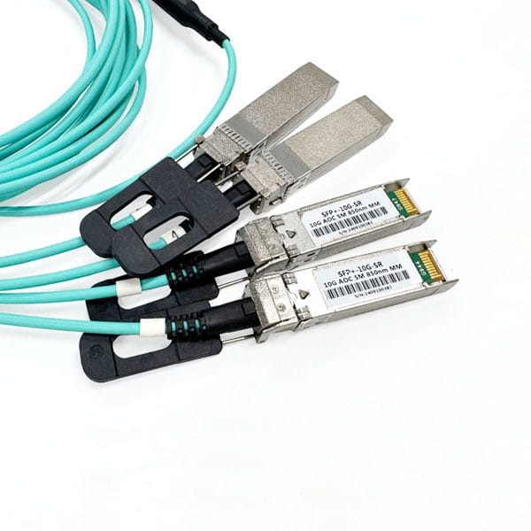
Advantages:
- Lower Cost: It eliminates the cumulative cost of separately purchasing one 40G transceiver, four 10G transceivers, and one MPO patch cord.
- Zero Contamination Risk: Since the fiber and transceivers are hermetically sealed and bonded internally, there is no need to clean fiber end-faces during installation; this eliminates the risk of “dust-induced end-face contamination causing packet loss,” making it a true plug-and-play solution.
- 100% Correct Wire Sequence: The wire sequence is permanently fixed at the factory by major chip manufacturers, eliminating any risk of human error regarding incorrect wire sequencing or polarity mismatches.
✅ Currently, 3 m or 5 m 40G-to-4x10G AOC cables represent the absolute mainstream and preferred solution for direct connections within the same cabinet.
Solution 2: Four 10G SFP+ ports distributed across different cabinets.
If these four 10G SFP+ endpoints are distributed across different cabinet slots (or even deployed across multiple cabinets), the complexity of the cabling infrastructure increases significantly. In such scenarios, the previously recommended AOC active optical cables or standard breakout cables are strictly unsuitable. The LC fanout pigtails are highly susceptible to breakage during the pulling and routing process between cabinets, and they lack the necessary length scalability.
For these distributed environments, you MUST adopt a customized breakout cables solution featuring enhanced protection and extended breakout lengths.
The following are the key cabling and design specifications:
1. Physical structure: Must incorporate an “armored/reinforced structure equipped with a breakout protector.”
- Reinforced Main Cable and Breakout Pigtails: For the MPO main cable section, a 4.5mm or 5.0mm reinforced, heavy-duty outer jacket is recommend. The 4LC duplex fanout pigtails must use either 2.0mm or 3.0mm cables featuring independent armor or braided mesh protection, no 0.9mm.
- Breakout Protector (Fan-out Kit): At the junction where the single MPO main cable splits into four LC pigtails, the manufacturer must install a breakout protector (fan-out kit) constructed from aluminum alloy or rigid plastic, complete with a strain-resistant armored boot. This ensures that during cross-cabinet cable routing, the tensile stress is beard by the breakout protector and the main cable, thereby preventing damage to the fragile optical fibers within.
2. Fan-out Length: Stepped Length Customization
Since the four terminal connectors are distributed across different cabinet slots, their physical distances from the core switch (40G port) vary significantly.
- Incorrect Approach: Making all four LC fan-out cables the same length (e.g., all 2 meters). This results in excessive cable slack accumulating in nearby cabinets, while cables reaching distant cabinets become taut and subject to strain.
- Correct Approach (Staggered Fan-out): Measure the actual distances to the specific cabinet slots on-site and order custom “staggered” lengths from the manufacturer.
- Example: DLC 1 fan-out length is 2 meters (connecting to a server in the local cabinet at the 5U position).
- Example: DLC 2 fan-out length is 5 meters (spanning to a server in adjacent Cabinet A at the 10U position).
- Example: DLC 3 fan-out length is 8 meters (spanning to a server in adjacent Cabinet B at the 20U position).
- Example: DLC 4 fan-out length is 10 meters (spanning to the more distant Cabinet C).

3. On-Site Cable Pulling and Error-Proofing Measures (Extremely Important)
- Factory-Installed Protective Pulling Eye: When placing an order with the manufacturer, it is mandatory to request the installation of a high-strength, braided nylon pulling net over the outer layer of the four LC duplex connectors. During installation—specifically when routing cables through cabinet side-panel ports or cable trays—personnel must *ONLY* pull on the pulling net’s loop. Once the cable pulling is complete, the net should be cut open to expose the underlying LC connectors. It is strictly prohibited to pull directly on the LC connectors or the thin fiber strands when routing cables through the cabinet.
- Dual Labeling at Both Ends: In addition to the standard number rings (1, 2, 3, 4) on LC connectors, a corresponding label identifying the target cabinet and rack unit position (e.g., DLC3 -> Cabinet B05-U14) must also be affixed at the “breakout” point on the MPO connector end.

4. Final Selection: Direct-Connect Breakout Cables vs. Structured Cabling
While scattered port requirements can be addressed using custom-length breakout cables, if the span exceeds two cabinets (or 15 meters), running such a direct cable would constitute a serious violation of the TIA-568 standard and would result in an extremely cluttered server room environment in the long run.
- If the total distance is < 10 m: The most economical solution is to utilize the specialized MPO-to-4LC breakout cables described above—specifically those featuring a thicker jacket, custom-stepped lengths, and a pulling eye.
- If the total distance is > 10 m or spans across multiple rows: It is strongly recommended to abandon the direct-connect approach immediately and revert to the standard TIA-568 Method B structured cabling architecture (MPO/MTP trunk cables + patch panels). A fixed backbone cable should be deployed between the core cabinet and the scattered cabinets, while standard, short LC patch cords are used to handle the internal cabling within each individual cabinet.
Conclusion
While using direct breakout cables for QSFP 40G to 10G is straightforward, the following details require careful attention:
1. All QSFP+ optical module ports on switches feature built-in pins (i.e.,MPO male connectors); we must use MPO female connector for the MPO-to-4LC breakout cables. If mixed, it is physically impossible to insert it into the optical module.
2. In addition to specifying the total length of the cable to the manufacturer, you must clearly define the fanout length of the LC pigtails (typically 0.5 m or 1 m). If the breakout section is too short, the four LC connectors will be unable to reach server ports located at a greater distance.
3. To prevent factory technical personnel from making this into a “non integrated receiving and transmitting” ordinary MTP trunk cable, please attach this paragraph directly when placing an order:
- Customization requirement: MPO (female) – 4 x LC duplex breakout cable.
- Line sequence requirement: It must be QSFP+ to 4xSFP+ dedicated transceiver crossover line sequence.
- Specifically: MPO’s P1 and P12 enter the first LC duplex connector; P2 and P11 enter the second LC duplex connector; P3 and P10 enter the third LC duplex connector; P4 and P9 enter the fourth LC duplex connector. The middle P5, 6, 7, and 8 holes are left blank. The MPO end must be Female (no-pins).”
According to this plan and script for procurement, upon arrival, the two ends can be directly plugged in, and the network can be 100% connected at once.