Skip to content
ANSI/TIA-568 is a comprehensive cabling standard for commercial buildings developed by the Telecommunications Industry Association (TIA). It specifies the design, installation, topology, and component performance of wiring systems for enterprise and data center networks, serving as one of the core specifications for building modern LANs and communication infrastructure globally, particularly in North America.
The TIA-568 standard includes multiple sub-documents, among which the optical fiber cabling standard specifies cable types, attenuation standards, and connector requirements for both multimode and singlemode fibers. Three key specifications primarily address MPO/MTP multi-fiber connectors.
- Polarity and Cabling System Standards (ANSI/TIA-568.3-D / E or the older version TIA-568-C.3): This is the core standard for multi-core parallel optical fiber, strictly defining three polarity wiring methods—Type A (straight-through), Type B (crossover), and Type C (pair crossover)—to ensure accurate alignment between the optical transmitter (Tx) and receiver (Rx).
- Comprehensive Cabling Standard (ANSI/TIA-568-C / D / E): Specifies the connection attenuation limits within the patch panel. For example, the standard defines the maximum allowable total loss for a standard patch panel (including one pair of MPO interconnections and front-end LC interconnections).
- Polarity Transition Standard (TIA-568.3-D Appendix): Standardizes the pre-wiring sequence within the patch panel (e.g., Base-8 or Base-12 architecture) to align with the overall system’s polarity design.
What is Method B scheme?
Method B is actually one of the three fiber polarity methods specified in the TIA-568.3-E standard. Its core purpose is only one: to ensure that the transmitting end (Tx) of high-density multi-core optical fibers (such as MPO/MTP systems) can be accurately connected to the receiving end (Rx) of the other end by combining cables (internal cable sequence) and adapters (flange physical structure), avoiding signal congestion or deadlocks.
In the TIA-568 standard, Method B is the most commonly used and error free structured cabling architecture for data centers to achieve smooth splitting from high bandwidth (40G/100G) to low bandwidth (10G/25G).
The core engineering logic is: “The two-level MPO/MTP trunk cables are completely flipped, and the MPO adapters are fully direct connected throughout the entire process” . By utilizing the physical principle of “negative equals positive” in two-stage Type B cables, the initial physical state is perfectly restored at the end, and finally, through the solidification and crossing of the MPO/MTP cassette, the “transceiver integration” of each LC port is achieved.
The following is the complete engineering design and technical disclosure white paper of the scheme.
Standard 12 Core/8 Core Color Code
Regardless of the manufacturer, the color sequence of the fiber core inside the optical fiber must strictly comply with the following standards:
| 1 | 2 | 3 | 4 | 5 | 6 | 7 | 8 | 9 | 10 | 11 | 12 |
| blue | orange | green | brown | gray | white | red | black | yellow | purple | pink | light blue |
✅Note: The 8-core MPO link used for 40G/100G typically uses 12 core physical plugs, leaving the middle holes 5, 6, 7, and 8 vacant, and only using the outer ends 1-4 and 9-12.
Product List and Polarity Regulations for Method B
In the standard Method B architecture, the hardware attributes of each node in the entire chain are strictly limited by official standards, and must not be mixed during procurement and construction:
- All 8/12-Fiber MTP/MPO cables (patch cables, trunk cables) must be Type B (Key Up – Key Up cables). The internal optical fiber is completely reversed. Pin 1 in, pin 12 out (1 ↔ 12, 2 ↔ 11…). The positioning keys on both ends of the connector are facing upwards in the same direction (Key Up).
- All MPO-MPO patch panel adapters must be Type A (Key Up – Key Down direct through adapter, not reversed). When fiber optic is plugged in, it only serves as a transparent physical connection and does not change any line sequence.
- B End cassette module must be a standard Method B certified conversion box (internal line sequence solidification cross, front panel LC duplex adapter, rear 1-2pcs MPO/MTP adapter).
Method B Working Principle
In order to thoroughly understand how the optical signal flips back and forth in the middle multi-level distribution frame, ultimately forming a “transceiver integrated” at the end LC port, please refer to the following strict working principle diagram and physical flow chart (taking channel 1 and channel 4 as examples):
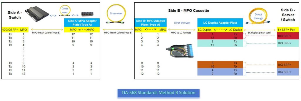
| Node location of the link | Channel 1 signal status | Channel 4 signal status | Core principle analysis |
| 1. A-end 40G QSFP+ port output | Hole position 1=Tx1 (sending signal) | Hole position 4=Tx4 (transmitting signal) | Switch native state:Left 4-core full hair, right 4-core full collection |
| 2. Pass through the first level Type B patch cable | Hole position 12=Rx1 (receive signal) | Hole 9=Rx4 (receive signal) | First flip:The cable has completed a 180 degree head to tail inversion inside |
| 3. Pass through the A-end Type A adapter | Convert to hole position 12 (carrying Tx1) | Convert to hole position 9 (carrying Tx4) | Adapter lossless straight through,Do not change any spatial line sequence |
| 4. Pass through Type B trunk cable | Convert to Hole 1 (carrying Rx1) | Convert to Hole 4 (carrying Rx4) | Second Flip:’Negative becomes positive’, the order returns to its original state |
| 5. Pass through B-end Type A adapter | Still at hole position 12 (carrying Tx1) | Still at position 9 (carrying Tx4) | The signal perfectly reproduces the initial physical arrangement |
| 6. Internal cross of conversion module (Cassette) | Still at hole 1 (carrying Rx1) | Still at position 4 (carrying Rx4) | End point gathering:Forcefully merge the sending and receiving of the same channel into the same LC |
| 7. Final delivery status | Restore to hole position 1 (carrying Tx1) | Restore to hole position 4 (carrying Tx4) | Perfectly connect 10G SFP+modules |
✅ Note: Due to the use of only 8 cores in 40G, the corresponding channels 5, 6, 7, and 8 in the backbone are left blank throughout and not enabled.
The Core Advantages of Method B
1. Post upgrade “zero excavation”: In the future, if the data center is upgraded from 40G to a pure parallel 400G network, the Type B MPO trunk cables and Type A adapter buried in the data center bridge or wall do not need to be removed at all. Simply unplug the MPO to LC cassette on the B-end and replace it with an MPO adapter panel to directly transmit parallel high-speed signals.
2. Reduce operation and maintenance error rate: Due to the fact that polarity crossing and integration are all fixed by dead hardware (inside the MTP LC cassette module), on-site operation and maintenance personnel only need to purchase the most common A-to-B cross LC LC duplex patch cords that can be seen everywhere in the market when connecting to servers, completely avoiding large-scale network interruptions caused by manual jumper polarity errors.
3. Convenient for high-density management: The connection interfaces on both sides of the core MTP patch panel are very neat, with all A ends having neat MPO interfaces and all B ends having standard 1U/2U high-density LC port interfaces.
Method B’s Testing Closed-loop Standard
Before inserting the MPO LC Cassette after laying the backbone and distribution frame, use an visual fault locator to conduct a lighting test on the A-end distribution frame. The physical presentation of the B-end distribution frame must meet the following requirements:
- Insert infrared light into hole 1 of the A-end distribution frame, and the corresponding adapter hole 1 of the B-end distribution frame must be bright.
- Insert infrared light into the 12th hole of the A-end distribution frame, and the 12th hole of the adapter corresponding to the B-end distribution frame must be bright.
Judgment criteria: If the bare view pin numbers of the MPO adapter plates on both ends of the distribution frame are completely consistent (in a straight through state), it means that the polarity loop of the backbone network has been successfully closed.
Conclusion
In the TIA-568 standard, Method B (scheme B) is the most commonly used polarity scheme in data centers, where flipping is entirely done inside the backbone cable. The operation and maintenance personnel are most relieved. The same standard MPO MTP patch cables can be used at both ends, which greatly reduces the inventory and error rate.
In actual fiber optic engineering cabling (especially in large data centers or data centers), please be sure to pay attention to:
① Unified throughout the entire link: Once Method B is selected, all backbone cables (Type B), adapters (Type B), and distribution boxes in the entire link must purchase Type B components.
② Avoid mixing: If the backbone of Method A is mistakenly used in the system of Method B, it may cause the optical path to be blocked (Tx is aligned with Tx), and may even be difficult to troubleshoot due to polarity confusion.
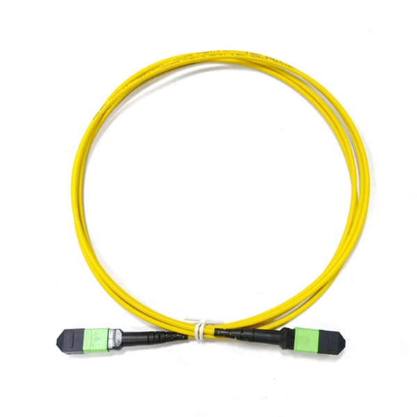
MPO MPO patch cord (Type B)
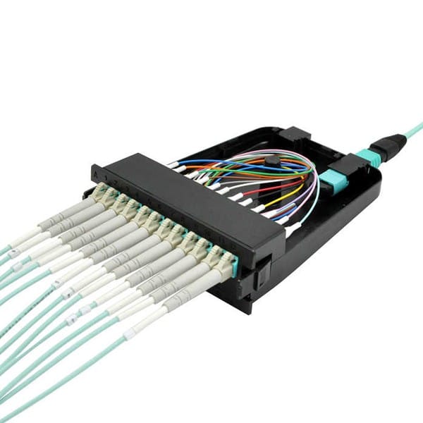
12 Fiber MPO LC Cassette (MPO adapter Type A)
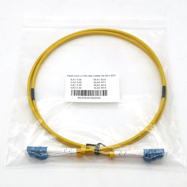
LC LC Duplex Patch Cords (A-B)
Yingda has been rooted in the optical communication industry for more than ten years, with rich production and case experience, reliable quality, fast delivery time, and worry free after-sales service. Contact us immediately for the best quote!