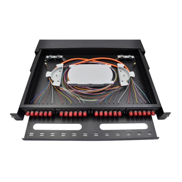
In enterprise data centers and telecommunication infrastructure, the Optical Distribution Frame (ODF) serves as the critical hub for fiber management. While network engineers and procurement teams often focus heavily on connector types (such as LC or SC), subtle specifications like buffer structures, jacket materials, and lengths are frequently overlooked.
Selecting the wrong fiber optic pigtail configuration can drastically slow down deployment timelines, increase insertion loss, or worse, lead to building fire code violations.
This comprehensive guide outlines the technical benchmarks for selecting and splicing ODF fiber pigtails based on real-world engineering standards.
1. Connector Selection: LC vs. SC Across Network Environments
The optimal pigtail connector and end-face polishing style depend entirely on your upstream active equipment and network architecture:
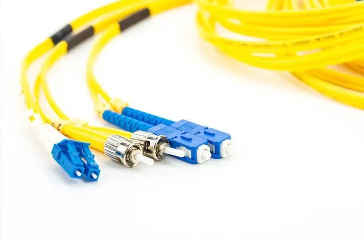
- Enterprise Data Centers (LC/UPC – Blue): Modern core switches, firewalls, and servers utilize high-density transceiver modules (SFP+, QSFP). For standard enterprise local area networks (LANs) utilizing Single-mode (OS2) or Multimode (OM3/OM4) fibers, LC/UPC (Ultra Physical Contact, Blue) is the default standard to maximize rack-unit density.
- Telecom & Broadband Access (SC/APC – Green): Telecom Passive Optical Networks (PON/FTTH) operate at higher transmission power. To minimize back-reflection that can damage laser components, industry standards mandate SC/APC (Angled Physical Contact, Green) connectors, which feature an 8-degree angled end-face to minimize return loss.
- Legacy Systems & Testing (FC/UPC – Metallic): Threaded FC connectors are highly vibration-resistant but bulky. They are primarily found in legacy transport equipment or specialized optical time-domain reflectometer (OTDR) testing instruments.
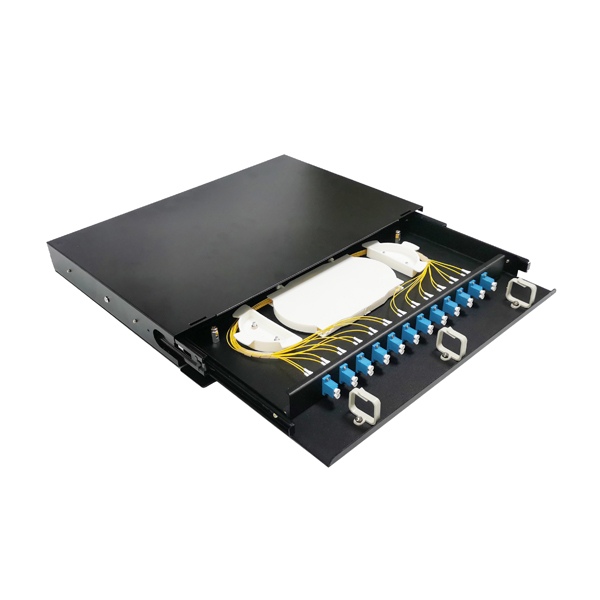
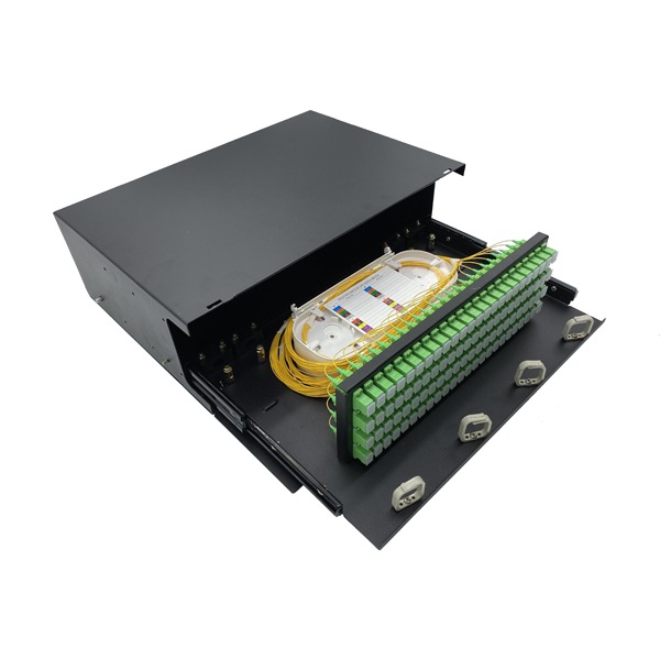
2. Buffer Structures: Why Semi-Tight Buffer Wins the ODF
Fiber pigtails are manufactured in three primary cable configurations. Understanding their mechanics is crucial for seamless installation:
📊 Buffer Structure Comparison
| Buffer Type | Construction Feature | ODF Suitability | Key Trade-off / Technical Risk |
| Semi-Tight Buffer (0.9mm) | Micro-gap between the 250μm coating and 0.9mm outer jacket. | Highly Recommended | Requires experienced splicing techniques to prevent fiber slippage. |
| Tight Buffer (0.9mm) | Outer jacket is extruded directly onto the 250μm coating. | Acceptable | Extremely difficult to strip over long lengths without damaging bare fiber. |
| Loose Tube | Fiber floats loosely inside a hard plastic tube filled with waterproof gel. | Strictly Forbidden | Gel leaks clog splicing trays and adapters; tube rigidness limits bending radius. |
- The Power of Semi-Tight Buffer: Because of the micro-gap design, technicians can effortlessly strip 1 to 2 meters of the outer jacket in a single pass using a standard fiber stripper without nicking the cladding. Furthermore, it provides excellent macro-bend protection within the compact ODF tray, allowing the glass fiber to self-adjust and relieve stress.
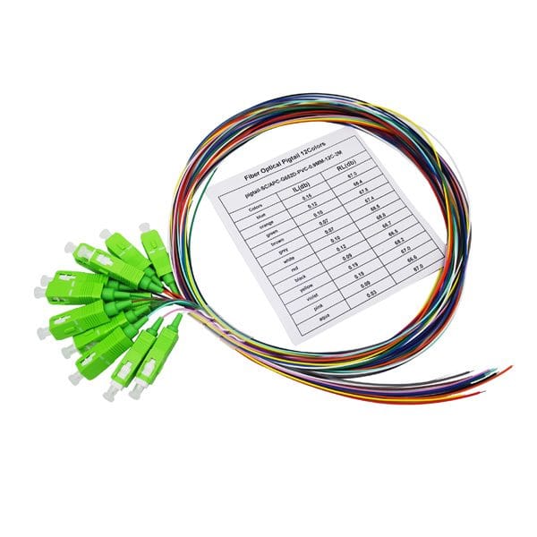
Semi-tight buffered Pigtails from Fiber Pigtail Manufacturer | Yingda, standard stock availability, fast delivery, competitive cost.
3. Length and Polarity Standards
- The 1.5-Meter Rule: Pigtail lengths should always be specified between 1.0m and 2.0m, with 1.5 meters being the industry sweet spot. Lengths under 1 meter do not leave enough slack to reach a desktop fusion splicer outside the chassis, nor do they allow for re-splicing margins if a splice fails. Lengths over 2 meters over-crowd the splicing tray, risking macro-bend attenuation due to cable pinching.
- TIA-598-A Color Coding: To avoid “cabling nightmares” when labels peel off over time, never use solid yellow pigtails in high-density ODFs. Standard procurement requires 12-color bundled pigtail kits following international color sequences (Blue, Orange, Green, Brown, Slate, White, Red, Black, Yellow, Violet, Rose, Aqua). This aligns perfectly with the multi-core backbone fiber cable for foolproof polarity verification.
4. 🔥 Engineering Insights: Stripping and Fusion Splicing FAQ
📋 FAQ 1: Should we specify LSZH or PVC for ODF pigtail jackets?
Answer: LSZH (Low Smoke Zero Halogen) is highly recommended and mandatory for modern infrastructure.
- Safety Compliance: LSZH compounds do not emit toxic halogen gases and produce minimal smoke when exposed to high heat, ensuring compliance with strict commercial fire codes. PVC releases thick, toxic hydrochloric acid smoke that corrodes expensive network switches.
- Stripping Performance in Winter: LSZH material maintains its flexibility across fluctuating temperatures. In freezing winter field environments, PVC jackets harden drastically, rendering normal stripping impossible. While an LSZH jacket can be stripped smoothly up to 2cm at a time, frozen PVC jackets break off in 2-3mm fragments, exponentially delaying fusion splicing workflows.
🛠️ FAQ 2: How should tight-buffer and semi-tight buffer pigtails be clamped in the fusion splicer?
Answer: Misplacing the fiber clamp position on the fusion splicer is the number one cause of high-loss splices or fiber retraction:
- For Tight-Buffer Pigtails: Since the outer jacket is firmly bonded to the internal glass cladding, you can position the splicer’s clamp directly over the outer 0.9mm jacket.
- For Semi-Tight Buffer Pigtails (Crucial Workaround): Because the jacket is designed to slide easily over the fiber, clamping down on the outer jacket will fail to secure the internal core. During the electric arc discharge or mechanical movement of the splicer, the glass core will experience micro-retraction, ruining the alignment. The correct technique is to strip the jacket slightly longer, allowing the splicer’s clamp to rest directly on the 250μm coating, mechanically locking the core in place.
5. Procurement and RFQ Specification Blueprint
When compiling your project’s Bill of Materials (BOM) or issuing a Request for Quote (RFQ) for network infrastructure, use the following standardized technical block:
- Diameter: 0.9mm single-core.
- Configuration: 12-Color Bundled Kit (TIA-598-A compliant).
- Length: 1.5 Meters.
- Buffer Type: Semi-Tight Buffer.
- Jacket Compound: LSZH (Low Smoke Zero Halogen) / Optional: OFNR/OFNP for plenum-rated projects.
- Connector Profile: LC/UPC (Enterprise) or SC/APC (Telecom).
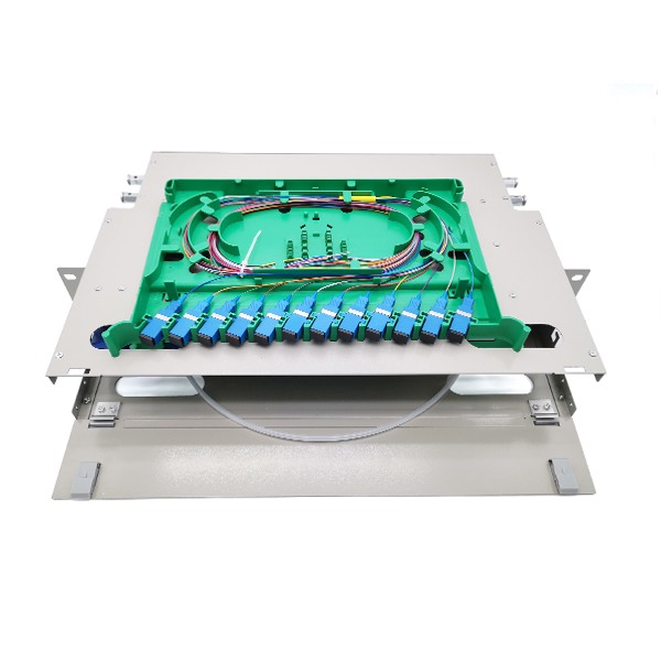
Yingda, as a ODF Fiber patch panel manufacturer, we help assembly pigtails and adapters in factory, welcome RFQ