Building Fiber-to-the-Home (FTTH) networks in low-density suburban and rural markets across North America poses a unique financial and structural challenge. Unlike high-density urban zones where centralized, balanced splitting trees (such as 1×32 or 1×64) are highly efficient, rural properties are frequently scattered along highways at intervals of several hundred feet to miles.
If you design a rural outside plant (OSP) using traditional uniform splitters, the amount of stranded fiber capacity and the upfront cable-trenching capital expenditure (CAPEX) can easily stall your return on investment (ROI).
To overcome this geographical constraint, regional ISPs, electric cooperatives, and OSP engineering firms are increasingly adopting Asymmetric Optical Tap Architectures (Linear Bus Topologies). In this technical guide, we break down why the 70/30 splitting ratio has become the industry benchmark and how to navigate the critical engineering trade-offs between Three-Window FBT (Fused Biconical Taper) and Full-Band PLC (Planar Lightwave Circuit) splitters during 10G XGS-PON upgrades.
1. The Physics of the Linear Bus Topology
In an asymmetric tap design, your distribution fiber behaves much like a transit bus line along a route. Instead of running home-run fiber strands from a central hub to every pocket of homes, a single distribution fiber feeds a continuous cascade of outdoor terminals.
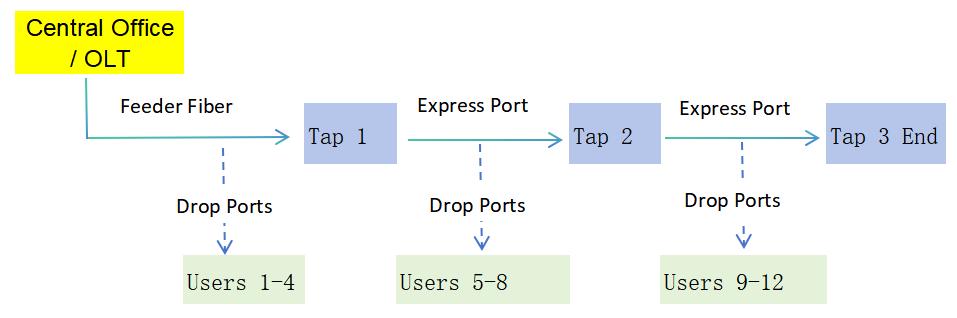
At each housing cluster, an unbalanced splitter intercepts the line. It “taps” a small percentage of the optical power to feed local subscribers via Drop Ports, while routing the remaining majority of the optical power downstream through an Express Port (Transit Port) to fuel the next terminal.
This approach minimizes OSP cable fiber counts, reduces field splicing points, and significantly speeds up deployment times in sparse rural corridors.
🛠️ COMMERCIAL BREAK: PROVE IT IN YOUR OWN LAB
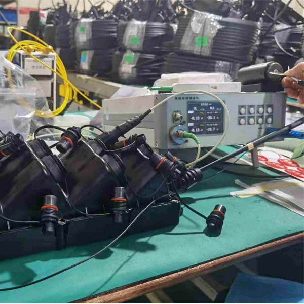
Designing a new network loop under BEAD or RDOF grants? Don’t rely purely on paperwork. We will ship a Free Engineering Sample Package (including our 70/30 ABS cassettes or rugged outdoor MST terminals) directly to your US facility for local lab evaluation.
➔ CLICK HERE TO REQUEST YOUR FREE TESTING SAMPLES
2. Why the 70/30 Ratio Profile is the Balanced Sweet Spot
In a linear network deployment, you cannot use the exact same splitting ratio at every single step. Because optical signals naturally attenuate over long distances, network architects utilize a Tapered Power Chain—deploying different unbalanced ratios depending on how far a terminal sits from the central office (OLT). A typical 5-stage chain cascades as follows:

Within this sequence, the 70/30 ratio (forwarding 70% of power downstream and dedicating 30% to local subscribers) is the highest volume SKU in outside plant procurement. Why? Because the 70/30 configuration provides an ideal optical power equilibrium in the mid-to-far segments of a rural loop. In fact, many operators deploying a simplified 3-stage inventory chain (85/15 ➔ 70/30 ➔ 0/100) will opt to use two 70/30 terminals back-to-back because its power loss profile allows for consecutive staging without crashing the link budget.
3. FBT vs. PLC Asymmetric Splitters: The Core Engineering Parameters
When procuring 70/30 unbalance taps, you will encounter two distinct manufacturing technologies: FBT and PLC. Understanding their physical limits is the difference between a reliable network and constant, expensive emergency field service calls (truck rolls).
Here is how their optical profiles stack up at room temperature and across full outdoor operating ranges:
| Performance Parameter | Three-Window FBT (1×2 Splitter) | Full-Band PLC (1×2 or Integrated 1×5 Matrix) |
| Passband Wavelengths | 1310±40nm / 1490±20nm / 1550±20nm | 1260 ~ 1650 nm (Full Optical Spectrum) |
| PON Technology Support | Legacy GPON / EPON / RF Video | GPON, XGS-PON, NG-PON2, 25G / 50G PON |
| Max Insertion Loss (IL) – Express | ≤ 2.0 dB | ≤ 2.2 dB |
| Max Insertion Loss (IL) – Drop | ≤ 5.8 dB (Single raw 30% drop) | ≤ 12.8 dB (Integrated 1×5 with 4 internal drops) |
| Polarization Dependent Loss (PDL) | ≤ 0.15 dB | ≤ 0.20 dB |
| Wavelength Dependent Loss (WDL) | N/A (Fixed window tuning) | ≤ 0.30 dB |
| Operating Temperature Range | -20°C to +75°C | -40°C to +85°C (GR-1209/1221 Compliant) |
4. The Critical Roadblock: 10G XGS-PON Compatibility
If your current network operation relies on standard GPON (transmitting 1490nm downstream and 1310nm upstream), Three-Window FBT asymmetric taps offer premium initial CAPEX savings. Because the fused fiber structure inside an FBT device creates very little scattering within those traditional legacy windows, its insertion loss on the Express port remains highly efficient (≤ 2.0 dB).
However, FBT has a hard technological ceiling.
Next-generation XGS-PON operates at 1270nm (Upstream) and 1577nm (Downstream). Because standard FBT devices are physically tuned only to legacy windows, passing XGS-PON frequencies through them causes out-of-band attenuation to skyrocket. Your 10G signal will experience massive insertion loss spikes and volatile Polarization Dependent Loss (PDL) fluctuations, resulting in severe packet loss or a completely dropped circuit.
Spectral Compatibility Mapping:
- FBT [1310nm/1490/1550nm]
- PLC [Full Band 1260nm – 1650nm]
The Solid-State Advantage of PLC Taps
To build a future-proof outside plant—especially when deploying infrastructure backed by federal subsidies—Full-Band PLC Asymmetric Splitters are an absolute prerequisite.
PLC technology utilizes semiconductor-like lithography to etch microscopic optical waveguides onto a silica substrate. This solid-state design treats all light between 1260nm and 1650nm identically. Whether you operate standard GPON today, switch to XGS-PON tomorrow, or overlay a full-spectrum OTDR monitoring line, the 70/30 splitting ratio remains rock-solid and completely flat.
Furthermore, because high-speed 10G and 25G PON protocols operate with significantly tighter optical power margins, they have zero tolerance for weather-induced signal flapping. FBT splitters can suffer micro-stretching in their fused zones during extreme winter-to-summer temperature swings. Our solid-state PLC asymmetric chips guarantee an ultra-low PDL shift (≤ 0.2dB) across extreme conditions (-40°C to +85°C), permanently eliminating temperature-driven emergency truck rolls.
📈 TECHNICAL SPECIFICATION ACCESS
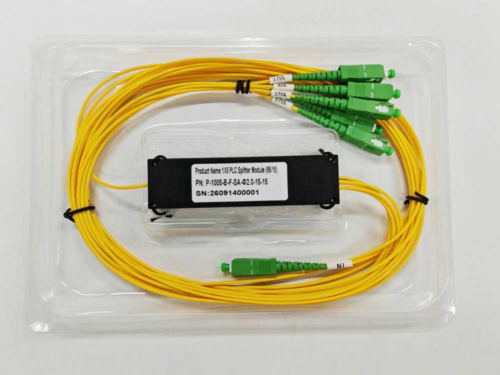
Want to evaluate the exact wavelength attenuation curves and packaging dimensions of our 70/30 and 85/15 profiles? Click below to instantly access our complete technical datasheets.
➔ DOWNLOAD THE SPECIFICATION SHEETS (PDF)
5. OSP Form Factors Tailored for North American Deployments
To minimize field splicing labor costs, our factory packages these asymmetric technologies into standard, ruggedized form factors ready for instant integration:
- Mini Steel Tubes (0.9mm Pigtails): Perfect for dense splice tray nesting inside traditional butt or inline splice cases.
- ABS Box Cassettes: Heavily jacketed loose tube outputs terminated with premium SC/APC (Green) connectors to ensure return loss values exceeding 60dB.
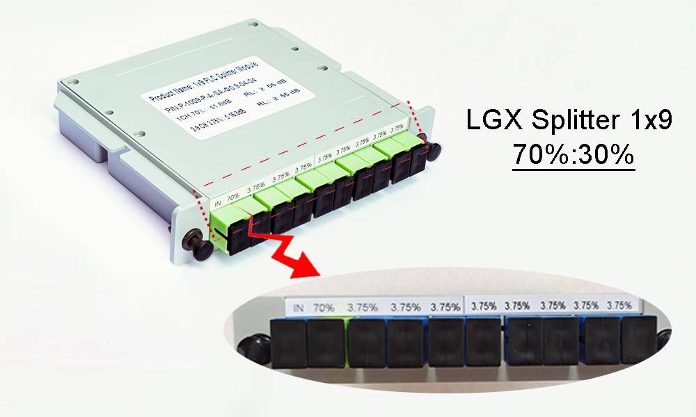
- LGX Rack Modules: Standard slide-in cards for central office racks or remote node cabinets.
- Hardened Multiport Service Terminals (MST): Factory-sealed, IP68 waterproof, and UV-resistant external enclosures. They feature integrated internal PLC 1×5 or 1×9 chips that handle the 70/30 split and divide the drop power evenly to external hardened drop ports—making subscriber turn-ups 100% plug-and-play for your field technicians.
Conclusion: Aligning Hardware with Business Strategy
Choosing the right asymmetric tap technology ultimately comes down to your long-term network roadmap:
- Opt for FBT 70/30 Taps if you are extending a traditional GPON footprint on a highly constrained budget where immediate component unit cost reduction is your primary metric.
- Opt for PLC 70/30 Taps if you are constructing modern, grant-funded infrastructure where an evolution to 10G XGS-PON or Combo PON is planned within the next few years. Investing in full-band stability upfront guarantees that you will never have to pay a crew to open up splice closures or replace field terminals when upgrading your central office electronics.
Have a unique link budget or custom cascading layout requirement? Contact our Application Engineering Support team at sales@ydfiberoptic.com to receive a complimentary optical pathway simulation.